
G8JNJ
About
- Username
- G8JNJ
- Joined
- Visits
- 3,965
- Last Active
- Roles
- Member
- Points
- 53
Reactions
-
Antenna recommendation for listening to faraway DRM broadcast inside a city
Hi All,
Well despite the rain I put the MLA-30 up in the air today.
It's a pretty poor performer, as the noise floor is about 20dB higher than any other active antenna I've tried, and increasing the amplifier gain doesn't help improve the Signal to Noise ratio.
There's also a lot of unwanted noise around 60 & 120KHz emanating from the DC-DC switcher in the Biasing Tee.
I've left it connected to one of my KiWi SDR's so that folks can try it for themselves.
http://southwest.ddns.net:8078/
You can use my other KiWi with a Loop on the ground as a reference.
http://southwest.ddns.net:8073/
Based on my tests, I wouldn't recommend it.
Regards,
Martin - G8JNJ
-
Bot appears on 517 khz with rapidly changing IP address
Could this simply be someone using a VPN that assigns a new IP address each time it reconnects ?
Regards,
Martin - G8JNJ
-
Antenna recommendation for listening to faraway DRM broadcast inside a city
Hi All,
I see that RTL-SDR.COM have mentioned the MLA-30.
https://www.rtl-sdr.com/reviews-of-the-low-cost-mla-30-wide-band-hf-magnetic-loop-antenna/
Best of all, on one of the sites mentioned Matt, M0LMK has boiled away the sealant goo and revealed the amplifier PCB. Well done :-)
https://www.m0lmk.co.uk/2019/09/12/inside-the-mla-30-active-loop-antenna/?fbclid=IwAR2G_OcFcLf5uAq8UqiTlXrw5NSpLQKrU-tWwGc_SUBFIcHj5PsSWeB5UKU
Speculation is that it uses a differential Input OpAmp/Line Driver such as a LMH6550.
Regards,
Martin - G8JNJ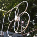
-
A question for the signal theory experts (Preamplifier gain)
>
>broadband magnetic loop, digital mode, there was no obvious advantage beyond about 3db (lowest) increase in noise floor
>
That's highly likely.
Glenn was spot on with his previous statement.
>
> It is more difficult to approach propagated and galactic noise floors with a small antenna, whether loop or dipole. It may not even be possible at mid-upper HF given typical >site signal levels and available active devices
>
With your loops and LZ1AQ amplifier, I suspect that the antenna performance is likely to be about 10dB worse than the sensitivity required to hear the galactic noise floor on the upper HF bands, so as soon as you see the noise from the amplifier raising the KiWi noise floor, you won't really notice any further improvement.
Very few (if any) 1m diameter active loops are capable of hearing down to the galactic noise floor on these frequencies, so it's not that you are doing anything wrong, it's just the laws of physics constraining things. There have been many previous threads on this subject if you wish to trawl back through them.
This is one of my gripes about Youtube videos where folks compare different receivers, but are using something like a Wellbrook loop as the antenna. In most cases the antenna is the limiting factor and not the actual receiver. In fact I despair about the trend with amateur transceivers where folks seem to gravitate towards equipment with very large dynamic range figures, whereas in all likelihood they will never be able to take advantage of it, because they are using compromise antennas in noisy urban environments. If you take a look at a lot of the KiWi's that are on line, many of them are struggling to achieve 20 or 30 dB dynamic range (max signal level to noise floor) for these reasons, so having a receiver capable of >120dB dynamic range is pointless.
I got close to achieving maximum sensitivity by using a combination of my TC2M broadband vertical, followed by a DXE-RPA1 copy 13dB low noise pre-amp and then a passive amplitude slope equaliser and selective BC band notches. By doing this I could have much greater RF gain on the HF bands, but roll it off on the LF bands where the natural noise floor was already higher than the KiWi baseline noise figure of somewhere around 14dB. However even this was not good enough to hear emissions from Jupiter at around 20MHz, which is what I was hoping for.
Regards,
Martin - G8JNJ