
G8JNJ
About
- Username
- G8JNJ
- Joined
- Visits
- 3,720
- Last Active
- Roles
- Member
- Points
- 16
Reactions
-
Quiet switch mode power supply (SMPS) for KiwiSDR
All the broadband routers I have had provided, have had noisy Switched Mode "Wall Wart" type power supplies as standard.
They produced far more interference than the routers, which generally tended to be of good construction and had been EMC tested as part of the design process.
The power supplies always seemed to be an afterthought, and may have been sourced differently from the actual router, depending on local electrical regulations and requirements.
It is likely that the power supplies have been chosen on the basis of cost, and we all know what happens then.
Because of their small size, it is usually not possible to add extra filtering, and such internal modifications can also result in safety and insurance issues.
I tend to look in Charity (Thift) stores or at Car Boot sales for older, cheap electronics, with separate linear power supplies. As it's difficult and expensive to buy new linear power supplies, especially since the audiophiles are willing to pay silly prices for them. The rest of the electronics are useful for parts too.
On an incidental, but related subject
A friend of mine, who allows me to host a KiWi at the historic Goonhilly satellite earth station in Cornwall UK, was good enough to resite the KiWi to a new location on the site, in an attempt to resolve some long standing interference problems. However, he couldn't get it to connect properly to the network. He could see it acquired a DHCP address, but he couldn't ping it. He then transferred the KiWi back to the original location, and it still didn't work properly.
Thinking that somehow the build had become corrupted, we arranged for him to return the KiWi to me, so that I could fix it, upgrade the OS and take the opportunity to check things like the fan (which as expected was stuck solid).
The actual fault was the Switched Mode Power supply, which seemed to be working correctly, as the output voltage was correct when checked with a multimeter, it would also still happily deliver 5A output.
However, I noticed that the output voltage dipped just a bit more than I would have expected when on load, but only by about 0.2v.
I took the power supply apart and discovered that the main high voltage DC storage capacitor (150uF at 450v) had dried out over time, and was completely open circuit. This is why the DC regulation was so poor, and also why the KiWi was having difficulties.
Replacing the capacitor fixed the problem, and the KiWi was back to working as normal.
Most of my past KiWi problems have been power supply related in one way or another, so my rule of thumb now is:-
If your KiWi is misbehaving in any way, check the power supply first, and pay close attention whilst you do it.
Regards,
Martin


-
Mouse wheel to tune the frequency? [added in v1.694]
I should have clarified the way it works a bit better.
Pushing the mouse wheel down whilst rotating it enables the opposite mode to the default that has been chosen. in OpenWebRX.
Having the possibility to tune using the mouse opens up other possibilities such as making your own VFO knob, using the optical encoder recovered from a scrap mouse, or buying one of the more expensive ready-made commercial items.
If it could be implemented in a way similar to that of OpenWebRX , then it would still retain the mouse wheel zoom option for those who prefer it, but offer an alternative for folks who would like to use mouse wheel tuning.
Try it and see for yourself.
If you open up the settings pane in the control panel, you should see the "Hold mouse wheel down to tune" tick box. Also set the tuning step size in the controls section, 500Hz or 1kHz is useful for SSB, as most folks use 'rounded up' frequencies.
I'm not specifically requesting this feature, as I don't wish to add to John's already massive workload of much more important issues, but I can understand the appeal of it.
Regards,
Martin


-
Private use of a KiwiSDR receiver in France
Hi Andy,
I understand the points you are making, but having previously discussed this with Philippe, I think there are some valid concerns, that may discourage other people, in other countries, from operating a KiWi.
If a simple fix, which John has already implemented, can help remove some of these barriers, then surely it is a good thing ?
Some countries are extremely sensitive about some aspects of the radio hobby, and to be honest, if I was living in one, I wouldn't be running a KiWi. It's easy to forget this when living somewhere that is more "relaxed" about such things.
Callsign piracy has always been an issue, and using an alpha-numeric string (or emojis) to identify an individual doesn't mean that they are who they say they are. However, I can understand the problem for the KiWi admin, if someone else decides to use your callsign, and you, the legitimate owner, find out, and then blame the admin for something that he has no control over. This may sound unlikely, but I have experienced similar problems when we had the "Chat" facility enabled on one of our websdr's, which caused so many issues we, (like most other websdr admins) removed it. Any public site, that has the ability for folks to anonymously post comments, no matter how brief in content, will unfortunately be abused.
Andy - "they" already know, who you are and where you are :-)
Regards,
Martin - G8JNJ ( or am I )

-
Map pins meaning
Hi Glenn,
I have used WSPR Daemon with good results, but unless you have set aside some KiWi channels to allow it to run, it's not really applicable to the average KiWi installation.
Although not calibrated against a known noise reference, the graphs I have obtained using the standard KiWi SNR stats are almost as detailed as the ones I obtained using KiWi Daemon, in therms of indicating propagation changes. But unlike WSPR Daemon, it's a background process and doesn't require additional resources such as a RasPi (scarce at the moment), or consume precicous receive channels in order to work.
In addition I feel that the use of WSPR is beginning to wane somewhat, and FT8 is now taking over the world of Amateur radio. In fact if FT8 had a mechanism for reporting transmitted power and a full 6 digit locator, as does WSPR, I think WSPR would be in further decline for use as a propagation indicator.
With this in mind, it would be nice if the KiWi could support more of the JT/FT modes as an extension, in addition to WSPR, as I believe the libraries are available, but I guess it's not particularly high on the adgenda for John these days.
Regards,
Martin
-
Quiet switch mode power supply (SMPS) for KiwiSDR
Sometimes, when used inside a Switched Mode Power supply, the additional choke inductor in the ground (L3 in the circuit) can sometimes be more problematic than useful.
I tend to wire the DC 0v / -ve directly to the mains earth, but depending upon the local configuration, this can also make things worse.
Unfortunately, it's one of those cases where, although it may be good practice to do certain things, you generally have to experiment, in order to find the best solution for your own setup.
Regards,
Martin
-
Please protect your KiwiSDR 2 from the high-level RF fields of nearby transmitters
Each of the DXE filters contains two filtered Halo HFJ-1G46ERL RJ45 sockets wired back to back on a small PCB.
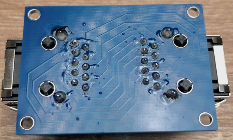
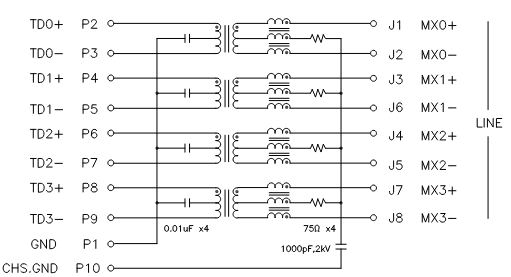
Pin 10 seems to be left floating in the DXE design.
Regards,
Martin
-
Enhancement: Add SYNOP-Decoder
Fldigi has a decoder, but I note that there are a number of Linux based parsers and decoders too.
Just a quick selection.
Regards,
Martin
-
Private use of a KiwiSDR receiver in France
Hi Philippe,
I'd agree with John that it doesn't make sense to list KiWi's that folks can't openly use.
But I do understand your reservations, and some countries are definitely more restrictive than others.
Short range local VHF / UHF communications are certainly more problematic from a legal perspective than HF communications, which generally tend to completely ignore geopolitical boundaries
Maybe it would be worthwhile emailing some of the other KiWi admin / operators in France, to see if they have the same concerns as yourself ?
Regards,
Martin
-
600 kHz wide mode
A bit more information for those interested in Wave Radars, cut an pasted links from discussions on other sites.
CODAR and WERA (now Helzel) are very similar systems, and I think that folks tend to call all of them CODAR, a bit like some brand names becoming used for all products of a certain type regardless of the actual manufacturer.
There are plenty of WERA systems operating, but maybe not in the USA, even so the chances are you will have heard one, but thought it was CODAR.
List of USA radars including manufacturer.
https://hfrnet.ucsd.edu/sitediag/stationList.php
You can also use this map.
https://cordc.ucsd.edu/projects/hfrnet/
Select station placemarks in the overlay menu to show them on the map.
If you click on each map pin it will give you more data, including the operating frequency.
Alternatively, there is this list, but it takes a very long time to load.
https://hfrnet.ucsd.edu/sitediag/stationList.php
WERA have a range of products, some of which have slightly different characteristics.
The European ones are listed in a table at the end of this document
https://eurogoos.eu/download/eu-hfradar-inventory-2016/?wpdmdl=9972&refresh=63f157c239dcf1676761026
An interactive on-line map of the current European sites can be found here.
https://eurogoos.eu/high-frequency-radar-task-team/
Regards,
Martin

-
600 kHz wide mode
They are Wave Radars, and sweep across the frequency range at a rate of approx 4Hz (250mS).
The ones you are hearing are most likely located at the Hook of Holland and Dyfamed in France, but there are likely to be other sources as it is a common frequency.
My KiWi's have most of the European ones marked with DX tags.
Regards,
Martin