
The KiwiSDR 2 online store is open for orders! Please visit kiwisdr.nz
G8JNJ
About
- Username
- G8JNJ
- Joined
- Visits
- 3,312
- Last Active
- Roles
- Member
- Points
- 400
Reactions
-
W/F and SND Bad Params
Hi Glen,
I was able to enter these commands directly via the KiWi admin console page.
I don't know if this is possible, but the responses I got back seem to indicate that it worked OK.
Regards,
Martin - G8JNJ
-
Seeed Metal case and GPIO connector
Hi Glen,
I think for me the main issue is that the interconnecting cables are not all bonded to the case at the point of entry with low impedance connections.
So RF currents will flow via separate routes across the PCB's and find various ways of interacting with the circuit components as a result.
By bonding at the point of entry, you preserve the screen around the whole assembly and don't provide an opportunity for differentials to be setup between cables.
Most of the cables connected to the KiWi are relatively straightforward and can easily be filtered and screened. However the Ethernet port is an exception, as this has its own filter network and balancing transformers contained within the actual PCB mounted Ethernet socket. The main issue with this, as far as I can tell, is that the components have been chosen to help comply with worldwide EMC regulations, most of which only apply above 30MHz. So their performance below this frequency, where we are mainly interested, can be somewhat hit and miss. If we can do away with the wired Ethernet connection, by using a USB WiFi dongle, then a lot of these problems simply disappear.
Here are some notes I copied from Keith Amstrong's very comprehensive notes on EMC compliance. They are free but you need to register your email address to be able to read them. They cover just about every aspect of EMC design, and you would have to complete a degree level training course, costing several thousands of pounds (or dollars) to have access to similar information.
The 'Past Articles' section is probably the quickest read, but it's worth taking a good look around if you have the time.
http://compliance-club.com/keitharmstrong.aspx
2.6.2 How shielded interconnections work
When a shield interacts with an EM-field, currents flow in the shield. Skin Effect makes RF currents travel on the surface of a shield, with current density diminishing with depth into the shields metal by 36% for every skin depth. The higher the frequency, or the more conductive the metal of the shield, the smaller is the skin depth. For good shielding effectiveness the shield should have many skin depths of thickness at the lowest frequency to be shielded. Skin effect is not described further here, but a useful reference is [8]. Figure 2P shows that providing we achieve our 360o shield coverage and 360o electrical bonding at shield joints, and have enough thickness in our shields metal given the frequency, the skin effect tends to force the external surface currents to flow on the outside of the shield, and the internal surface currents on the inside.
4.3.9 Near-field leakages through apertures
So far we have assumed that the source was so far away that its EM radiation was plane waves, i.e. the shield was in the far-field of the radiating source - the usual situation when trying to protect electronics from external RF sources (to improve immunity).
But when using shielding to reduce emissions from a product, the shield is usually in the near-field of the source - and the SE from plane wave assumptions can be very wrong indeed, especially at lower frequencies. The closer the RF source is to the apertures, the worse the SE. Very significant amounts of leakage can occur, especially at low frequencies, even through arrays of very small apertures that have very low SE for plane (far-field) waves, see [17] for more detail.
Figure 4R sketches the E and H fields around an aperture, indicating that they are associated with regions of reduced SE, where it would be inadvisable to locate noisy or sensitive components or conductors.
This is how to make 'sniffer' probes that you can use with your KiWi to track down interference sources.
1.1 Close-field probes
Close-field (also called 'near-field') magnetic and electric field probes are low-cost to buy and very quick and easy to make. They are commonly used in development, diagnostic and QA work. There are many articles and papers describing how to make various versions of such probes, and most EMC test equipment manufacturers also sell their own versions of them. Figure 1 shows the three main constructions for magnetic field probes.
Near-field probes should always use 50R cables, and the input impedance of the RF measuring instrument they are connected to should also be 50R. Where the test instrument does not have a 50R input option, use its high-impedance input but fit a 50R BNC terminator at the instrument end of the probe's cable, for example using a BNC 'Tee' piece or through-line terminator. The 50R termination helps stop resonances in the probe cable which would otherwise occur when its length exceeds one-tenth of the wavelength of the highest frequency of interest (e.g. 50R termination is necessary for cables longer than 300mm for a highest frequency of only 50MHz - remembering that the wavelength for a signal in a cable is roughly half that of an electromagnetic wave in free space).
Figure 2 shows a standard electric field probe design, and also a 'pin probe'. The pin probe is a voltage probe which makes contact to the circuit or metalwork of interest via a 10pF capacitor, and it picks up the common-mode (CM) voltage as well as the signal voltage. CM voltage is a big contributor to radiated emissions. Magnetic field probes are shielded so that they don't pick up electric fields, which can sometimes leave them 'blind' to an important source of emissions. Usually, for small products, it is the CM currents leaking out via cables that cause most of the radiated emissions, but sometimes it is the electric field caused by the CM voltage on the body of the EUT itself, so electric field or pin probes have an important part to play.

Regards,
Martin - G8JNJ
-
W/F and SND Bad Params
Hi Glen,
I was able to enter these commands directly via the KiWi admin console page.
I don't know if this is possible, but the responses I got back seem to indicate that it worked OK.
Regards,
Martin - G8JNJ -
Seeed Metal case and GPIO connector
Hi All,
I've had some issues with radiated noise from a KiWi that I installed on a shared site. The main issues were that it was interfering with of VHF satellite reception and degrading the GPS performance of another system in the same room.
The KiWi was installed in the Seeed metal case, and I had fitted ferrites to the cables.
As I'm currently building up a KiWi for installation at another site, I thought that it would be a good idea to see if I could further reduce the level of emissions from a KiWi fitted in the Seeed case.
In order to do this I used an EMC H-Probe consisting of a 1"diameter screened loop connected to a spectrum analyser, in order to see what the level of emissions looked like and where they were escaping from the case.
The majority of the noise was leaking out through the holes in the ends of the case and also via the additional interconnecting cables I had fitted to bring out the GPIO ports for antenna switching.
This shows the general level of radiation from a KiWi without a case, with the Seeed metal case and with the Seeed case and additional modifications. Note that the measurements were made without the external GPIO cable connected.
The next shot shows the difference between the Seeed metal case and with the Seeed case and additional modifications in more detail.
As you can see the biggest difference is achieved by fitting the metal case, and I would definitely recommend doing this if you are still using the plastic frame supplied with the KiWi.
However there is still a fairly significant amount of radiated noise throughout the whole spectrum, especially in the VHF / UHF / Microwave range, and the only way to cure this is to close up the holes in the box.
As I didn't want to restrict airflow and ventilation I used some very fine woven brass mesh that I previously bought for antenna construction.
I added a section of mesh at each end of the box and sandwiched it between the end plates and the box sides, having first cutout suitable holes for the connectors I still wished to use.
Note that I had to solder short brass sheet straps between the Ethernet port metal socket surround and the mesh and also the -ve of the DC input connector where it enters the board (prior to the common mode choke on the board) in order to reduce the level of radiated noise from the external screened CAT5 Ethernet cable and DC power cable. There already was physical / electrical contact between the mesh and Ethernet connector, but I noticed that the screening effectiveness varied as I flexed the cable, and I didn't want to risk problems on-site at a later date if the mesh tarnished or developed an oxide layer.

Here are a couple of external views, showing the wire mesh with the case closed.

Once I had done this work I still had some noise from the GPIO port, so I added some 0.1uF decoupling capacitors and some 1/8th watt 1K Ohm resistors in series with the wires from the KiWI GPIO pins (not the 0v ground return) and the decoupled pins of the output connector. This also provided some short circuit protection, as previously suggested as best practice earlier in this thread.

After doing all of this work, the level of emissions are now minimal, and the ambient level of noise in my workshop is higher than the majority of noise produced by the KiWi, even though the close field probe is right next to the case. There is still a bit of radiation along the seams between the top and bottom case halves, but this is very low level, and if necessary can be further reduced by running self adhesive aluminium (ducting) tape over the seams.
One other interesting observation is that before fitting the mesh and additional earth bonding strap, I didn't find that using screened Ethernet cable made much difference to the level of noise radiated around 20MHz. However after performing the modification it's really noticeable that using screened cable makes a big difference.
Overall I think the additional mods are worth doing, especially if you are bringing the GPIO pins out of the box. But if you are already housing your KiWi in a diecast box with suitable cable bonding, then you are probably already experiencing most of the benefits I have observed.
Regards,
Martin - G8JNJ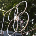
-
Seeed Metal case and GPIO connector
Hi All,
I've had some issues with radiated noise from a KiWi that I installed on a shared site. The main issues were that it was interfering with of VHF satellite reception and degrading the GPS performance of another system in the same room.
The KiWi was installed in the Seeed metal case, and I had fitted ferrites to the cables.
As I'm currently building up a KiWi for installation at another site, I thought that it would be a good idea to see if I could further reduce the level of emissions from a KiWi fitted in the Seeed case.
In order to do this I used an EMC H-Probe consisting of a 1"diameter screened loop connected to a spectrum analyser, in order to see what the level of emissions looked like and where they were escaping from the case.
The majority of the noise was leaking out through the holes in the ends of the case and also via the additional interconnecting cables I had fitted to bring out the GPIO ports for antenna switching.
This shows the general level of radiation from a KiWi without a case, with the Seeed metal case and with the Seeed case and additional modifications. Note that the measurements were made without the external GPIO cable connected.
The next shot shows the difference between the Seeed metal case and with the Seeed case and additional modifications in more detail.
As you can see the biggest difference is achieved by fitting the metal case, and I would definitely recommend doing this if you are still using the plastic frame supplied with the KiWi.
However there is still a fairly significant amount of radiated noise throughout the whole spectrum, especially in the VHF / UHF / Microwave range, and the only way to cure this is to close up the holes in the box.
As I didn't want to restrict airflow and ventilation I used some very fine woven brass mesh that I previously bought for antenna construction.
I added a section of mesh at each end of the box and sandwiched it between the end plates and the box sides, having first cutout suitable holes for the connectors I still wished to use.
Note that I had to solder short brass sheet straps between the Ethernet port metal socket surround and the mesh and also the -ve of the DC input connector where it enters the board (prior to the common mode choke on the board) in order to reduce the level of radiated noise from the external screened CAT5 Ethernet cable and DC power cable. There already was physical / electrical contact between the mesh and Ethernet connector, but I noticed that the screening effectiveness varied as I flexed the cable, and I didn't want to risk problems on-site at a later date if the mesh tarnished or developed an oxide layer.
Here are a couple of external views, showing the wire mesh with the case closed.
Once I had done this work I still had some noise from the GPIO port, so I added some 0.1uF decoupling capacitors and some 1/8th watt 1K Ohm resistors in series with the wires from the KiWI GPIO pins (not the 0v ground return) and the decoupled pins of the output connector. This also provided some short circuit protection, as previously suggested as best practice earlier in this thread.
After doing all of this work, the level of emissions are now minimal, and the ambient level of noise in my workshop is higher than the majority of noise produced by the KiWi, even though the close field probe is right next to the case. There is still a bit of radiation along the seams between the top and bottom case halves, but this is very low level, and if necessary can be further reduced by running self adhesive aluminium (ducting) tape over the seams.
One other interesting observation is that before fitting the mesh and additional earth bonding strap, I didn't find that using screened Ethernet cable made much difference to the level of noise radiated around 20MHz. However after performing the modification it's really noticeable that using screened cable makes a big difference.
Overall I think the additional mods are worth doing, especially if you are bringing the GPIO pins out of the box. But if you are already housing your KiWi in a diecast box with suitable cable bonding, then you are probably already experiencing most of the benefits I have observed.
Regards,
Martin - G8JNJ -
Seeed Metal case and GPIO connector
Hi All,
Just some brief notes regarding the installation of a 15 way D connector on the Seeed metal case in order to bring out the GPIO port for use with an antenna switch.
The ventilation slot cuts out very easily and only required a small amount of filing in order to make the connector shell fit.
First the pinout I used
End view of case
Top view of connector
Wiring to GPIO ports
Side view
Hope this is of some use to others.
Regards,
Martin - G8JNJ
-
Seeed Metal case and GPIO connector
Hi All,
I've had some issues with radiated noise from a KiWi that I installed on a shared site. The main issues were that it was interfering with of VHF satellite reception and degrading the GPS performance of another system in the same room.
The KiWi was installed in the Seeed metal case, and I had fitted ferrites to the cables.
As I'm currently building up a KiWi for installation at another site, I thought that it would be a good idea to see if I could further reduce the level of emissions from a KiWi fitted in the Seeed case.
In order to do this I used an EMC H-Probe consisting of a 1"diameter screened loop connected to a spectrum analyser, in order to see what the level of emissions looked like and where they were escaping from the case.
The majority of the noise was leaking out through the holes in the ends of the case and also via the additional interconnecting cables I had fitted to bring out the GPIO ports for antenna switching.
This shows the general level of radiation from a KiWi without a case, with the Seeed metal case and with the Seeed case and additional modifications. Note that the measurements were made without the external GPIO cable connected.
The next shot shows the difference between the Seeed metal case and with the Seeed case and additional modifications in more detail.
As you can see the biggest difference is achieved by fitting the metal case, and I would definitely recommend doing this if you are still using the plastic frame supplied with the KiWi.
However there is still a fairly significant amount of radiated noise throughout the whole spectrum, especially in the VHF / UHF / Microwave range, and the only way to cure this is to close up the holes in the box.
As I didn't want to restrict airflow and ventilation I used some very fine woven brass mesh that I previously bought for antenna construction.
I added a section of mesh at each end of the box and sandwiched it between the end plates and the box sides, having first cutout suitable holes for the connectors I still wished to use.
Note that I had to solder short brass sheet straps between the Ethernet port metal socket surround and the mesh and also the -ve of the DC input connector where it enters the board (prior to the common mode choke on the board) in order to reduce the level of radiated noise from the external screened CAT5 Ethernet cable and DC power cable. There already was physical / electrical contact between the mesh and Ethernet connector, but I noticed that the screening effectiveness varied as I flexed the cable, and I didn't want to risk problems on-site at a later date if the mesh tarnished or developed an oxide layer.
Here are a couple of external views, showing the wire mesh with the case closed.
Once I had done this work I still had some noise from the GPIO port, so I added some 0.1uF decoupling capacitors and some 1/8th watt 1K Ohm resistors in series with the wires from the KiWI GPIO pins (not the 0v ground return) and the decoupled pins of the output connector. This also provided some short circuit protection, as previously suggested as best practice earlier in this thread.
After doing all of this work, the level of emissions are now minimal, and the ambient level of noise in my workshop is higher than the majority of noise produced by the KiWi, even though the close field probe is right next to the case. There is still a bit of radiation along the seams between the top and bottom case halves, but this is very low level, and if necessary can be further reduced by running self adhesive aluminium (ducting) tape over the seams.
One other interesting observation is that before fitting the mesh and additional earth bonding strap, I didn't find that using screened Ethernet cable made much difference to the level of noise radiated around 20MHz. However after performing the modification it's really noticeable that using screened cable makes a big difference.
Overall I think the additional mods are worth doing, especially if you are bringing the GPIO pins out of the box. But if you are already housing your KiWi in a diecast box with suitable cable bonding, then you are probably already experiencing most of the benefits I have observed.
Regards,
Martin - G8JNJ -
More GPS Problems - Damaged hardware?
Some further notes for anyone who may pick up this thread at a later date and wish to copy this information.
If you wish to split the GPS signal from the antenna to feed multiple KiWI's.
Do not attempt to simply use a tee adaptor or similar to split the feed, as this will introduce unpredictable impedance excursions on the coax cables, which is turn will result in very deep 'notches' in the signal amplitude at various frequencies.
You can only use passive splitters if the antenna has sufficient gain to overcome the splitting losses and cable losses ahead of the KiWi.
2 way split = approx 3.5dB additional loss
3 way split = approx 5dB additional loss
4 way split = approx 7dB additional loss
Try to find passive splitters that only have a DC pass on one port. This will save having to fit additional external DC blocks in order to prevent one KiWi feeding DC back into another via the GPS connectors.
Make sure they are rated up to 2GHz, like this model / style
https://www.amazon.com/Ideal-85-332-2-Way-Digital-Splitter/dp/B003QM9UHS/ref=sr_1_2?keywords=ideal+2+way+splitter&qid=1563704237&s=gateway&sr=8-2
https://www.amazon.com/Ideal-85-334-4-Way-Digital-Splitter/dp/B003V18KQ6/ref=sr_1_3?keywords=ideal+4+way+splitter&qid=1563704346&s=gateway&sr=8-3
You can obtain 'F' type male to SMA male patch cables on Ebay at under $4 each. It's better to buy ones that are longer than you need, so that there is room to wrap them around ferrite rings if required. Make sure you choose the correct sex of connectors, as reverse SMA is quite common.
https://www.ebay.com/itm/RG316-Cable-F-Type-male-plug-to-SMA-male-plug-RF-Pigtail-Coax-Jumper/273406498020?hash=item3fa84c14e4:m:mFvLi09dwBokRt1mcM3MNiQ
Hope this helps anyone else following in these footsteps.
Regards,
Martin - G8JNJ
-
More GPS Problems - Damaged hardware?
Hi Chris,
I use passive satellite TV splitters with an inbuilt DC block (or steering diodes) on all but one port.
This sort of thing with suitable adaptors.
I use a two way to feed two more two ways, so that I can feed the office and workshop (Trimble) with a mid point split, This gives about about 7-8dB loss in total on each leg, which is fine with an antenna with 40dB of amplification.
Regards,
Martin - G8JNJ
-
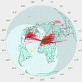
TDoA background maps not loading
>
>John, is it possible to have the basic (landmass boundaries) maps that TDoA used when I first got my Kiwi last summer?
>Presumably the multiple TDoAs I do when I TDoA in order to see the results "group" requires the same map tiles be loaded that many >times. I'm only interested in the coordinates. Landmass boundary maps I'm guessing might not have that problem... but then what do I >know?
>
Brett's suggestion is a good one.
I use the TDoA function a lot, and I'm concerned about the costs to John associated with the provision of maps.
Maybe have the option for no map, just the co-ordinates overlay, then once you have got a good plot you can re-run it with the required map turned on. This would save downloading tiles and additional cost.
Regards,
Martin - G8JNJ
