
G8JNJ
About
- Username
- G8JNJ
- Joined
- Visits
- 4,661
- Last Active
- Roles
- Member
- Points
- 130
Reactions
-
Any idea what this is?
I seem to vaguely remember that VARA HF modem has a test / setup mode that generates sweeps.
However, I can't find an example, so I may be wrong.
Regards,
Martin

-
VDSL filter for the Kiwi SNR measurement
I agree that the SNR measurement function is flawed, and appreciate that you, John, may have spent more time on it than you would like. However, even in its current form it is far better than having nothing at all.
This is especially true when using TDoA, as it allows you to see at a glance which KiWi's would definitely not be useable for such purposes, and this "pre sorting" saves a LOT of time and otherwise wasted effort.
Likewise, by providing SNR colour coded markers on the KiWi maps, it is easy to see which ones are likely to provide reasonable reception. As only about 10% of the 800+ KiWi's deployed worldwide produce relatively noise free performance. It would take a long time to find these among the vast majority of poorly performing ones, without some sort of SNR or other quality indicator being in place.
I'd also suggest that the SNR value, performs a useful function in encouraging KiWi owners to consider improving their antenna systems, and chasing down interference sources.
Overall, I think the SNR measurement has had a positive influence on the KiWi network, as a type of quality control, and that without it, there would be many more poorly performing KiWi's in operation.
Regards,
Martin

-
VDSL filter for the Kiwi SNR measurement
Ah OK, however it would be interesting to see if John's filter, also responds to broadband noise that looks like VDSL.
I wonder if there are several consecutive FFT bins, that contain the same level, could this be interpreted as wideband noise rather than individual signals, and treated as such in the SNR calculation ?
Regards,
Martin

-
Is my KiwiSDR about to fail?
I'd suggest checking your power supply, as an initial part of any investigation..
I've had similar problems, and it's nearly always turned out to be power supply related.
On particular problem is poor quality electrolytic capacitors that "dry" out over time, and the power supply smoothing and regulation suffer as a result. This is not always immediately obvious, but sometimes becomes more apparent when the KiWi and Beagle draw more current during certain operations.
Regards,
Martin
-
Very wideband FSK(?) on 40m
Well done on the TDoA, especially as it doesn't work too well on CW or FSK. I made several TDoA runs during grey line propagation, and initially thought it was from Germany. I should have known better. I used two separate browser instances with my KiWi, with the frequencies offset to produce a composite, but much narrower shift FSK signal, that I could attempt to read with an external decoder. However, the data is encrypted, as you would expect for a military signal.
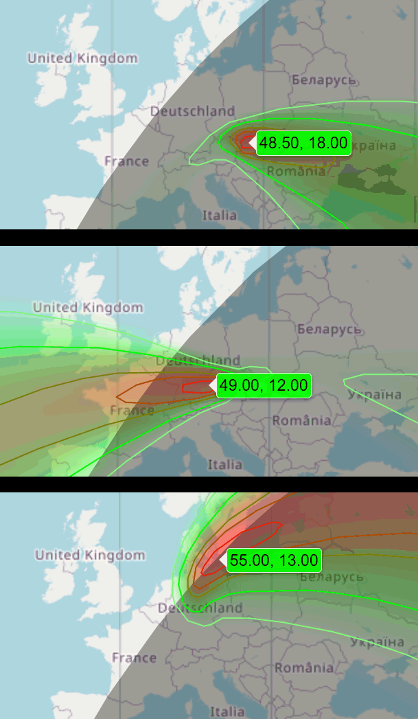
The pair on 7043/7050 kHz shift to 7041.5/7048.5 kHz
The pair on 7063/7070 kHz shift to 7061.5/7068.5 kHz
Reports and discussion suggest it's a Russian FSK transmission, with some reports suggesting it's coming from somewhere in the Urals or the heart of Siberia, but one more detailed report suggests that the source is in the Crimea near Sevastopol ( https://youtu.be/zRho2iFfBCE )
--- Text from YouTube video---
Sevastopol; Extremely powerful two channel 20b/7000 Hz FSK paired signals re-appear from Apr 23rd on 40m band ~ 7045cf and 7065.5cf, each channel seems to be 7 kHz from mark and space, chosen for it's immunity from being easily jammed, at times the pair will shift frequency; originating from Eastern EU / Western RU region, now Crimea with transmitters near Sevastopol. The modulation rate of 20b with a shift of 7000 Hz.
-The signal frame is 17 bits, the first of which is a 0.
-The superframe is 15 frames (255 bits) and is constantly repeated so it does not appear to carry any useful information
Military encryption 5N1 use in related signal connection to the conflict between Ukraine and Russia is likely. Contributor ANgazu thank you for your analysis!
---
This link has a similar discussion and explanation as to these signals:
https://reflector.sota.org.uk/t/some-weird-cw-found-on-40m/38289?u=iu1kgs

-
What are these downchirp transmissions ?
These are typical of RF welding / Drying / Curing processes. Very high power RF sources are also used during some types of semiconductor manufacturing processes.
Another source, is from the cheap Chinese "Radio Frequency Facial Machine" or "wands". These typically produce between 5 to 25 watts, but some are rated at several hundred watts.
All of the above can usually be observed around most of the ISM allocations, and they are a good propagation indicator on the low VHF bands.
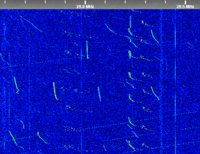
Here are a few that should really be in the 40MHz ISM band, most likely from Asia.
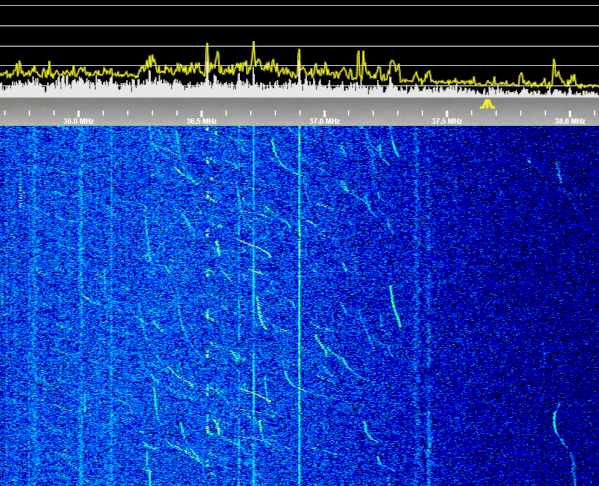
When I used to live in an industrial town, we had one in a factory that welded seams on industrial clothing, that operated on 27MHz, and the Interference Investigators were forever chasing the owners, as they often removed safety covers, so that they could run the machine for longer before it overheated. The stray RF signals and harmonics used to interfere with the 2m amateur band and local taxi services over a very large radius. Once you have heard the distinctive warbling, humming, and drifting signals, you can easily spot them again.
Regards,
Martin

-
Number station on 8992Khz?
It's a common US HFGCS frequency, and they are sending an encoded Emergency Action Message (EAM)
Nothing to worry about (yet) these are very common transmissions.
But I'm pleased your SNR is creeping up :-)
Regards,
Martin

-
Sitting my Ham license :-)
Good luck.
I don't use mine that much, but if you are interested in radio, it's always handy to have an amateur licence.
In the past, it used to be a valuable "pseudo" technical qualification when seeking employment, but those days are long gone.
Have fun,
Martin
-
HT004a / LNA / Anyone used one?
Hi Glenn, I don't disagree, which is why I stated "Any further improvement can only be brought about by using a better antenna, or by reducing the amount of noise present by some other method."
If for example you have a problem with noise induced into the transmission line, amplifying and balancing at the antenna, then attenuating at the receiver, can reduce the noise contribution. This is only one example, but as you have said "sometimes, even if for the wrong reasons, a preamplifier might improve performance".
The point I was trying to make is that by just adding extra gain, it usually doesn't make things any better. It requires considered thought to do it correctly.
Regards,
Martin
-
HT004a / LNA / Anyone used one?
That amplifier uses the same Qorvo TQP3M903 device, so I'd assume it's the same circuit too.
As before, the IMD performance isn't really sufficient for use ahead of a KiWi.
SV1AFN produces some good amplifiers that work well.
Although no longer a standard product, on request, he can also produce active splitters using push-pull pairs of FET's that work well. They have been successfully used at the Weston KiWi cluster, where we previously had severe problems with strong medium wave signals from nearby transmitters.
Turn Island Systems also produce a filtered pre-amp, using a Mini-Circuits device. Although the IMD specification is not too good, the use of a shelving and low pass filter ahead of it, minimises the performance issues.
I have no commercial interest in these companies, and do not specifically recommend them. I have simply highlighted them because of their characteristics, which may make them useful to KiWi owners.
Regards,
Martin