
G8JNJ
About
- Username
- G8JNJ
- Joined
- Visits
- 4,300
- Last Active
- Roles
- Member
- Points
- 100
Reactions
-
Please protect your KiwiSDR 2 from the high-level RF fields of nearby transmitters
Each of the DXE filters contains two filtered Halo HFJ-1G46ERL RJ45 sockets wired back to back on a small PCB.
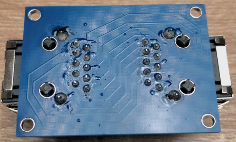
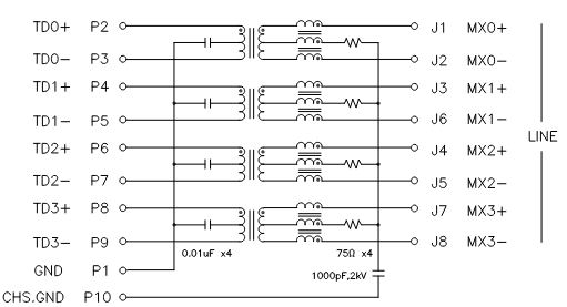
Pin 10 seems to be left floating in the DXE design.
Regards,
Martin

-
Does this PSU seem adequate for two KiwiSDR's?
Everything is inside the box as shown by the dotted line.

-
Mouse wheel to tune the frequency? [added in v1.694]
I should have clarified the way it works a bit better.
Pushing the mouse wheel down whilst rotating it enables the opposite mode to the default that has been chosen. in OpenWebRX.
Having the… (more)


-
Adding Kiwi to my website
Hi All,
Details of my 'Loop on the ground' (or technically just above it) can be found on this webpage.
https://www.g8jnj.net/loop-on-the-ground
Treat the page as a preview as it's more of a working… (more)

-
RSDN-20 beacons reactivated on 11.9, 12.65 & 14.9KHz
Hi All,
The Russian RSDN-20 beacons on 11.9, 12.65 & 14.9KHz are active once again after quite a long absence.
They must have found some more coins for the electricity meter down the back of their… (more)