
G8JNJ
About
- Username
- G8JNJ
- Joined
- Visits
- 3,965
- Last Active
- Roles
- Member
- Points
- 53
Reactions
-
5Mhz Aero / licence required?
They are most likely pirates, probably fishermen.
They often like to find "private" frequencies in order to conduct their "private" conversations, and these tend to be on frequencies with number sequences that are easily remembered.
There tend to be lots of them speaking all sorts of Asian languages, and frequently performing lots of chanting.
5 to 12MHz seems to be the most used frequency ranges, but they can pop up almost anywhere.
Regards,
Martin

-
Wonder what this is at 5300Khz? - its always there.
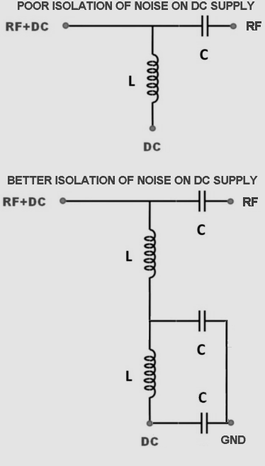
As I said previously, the majority of Bias Tees have very poor filtering between the DC line and the RF path.
Nearly all the circuits you find on the internet tend to be outlining theoretical designs, that concentrate on providing the least attenuation and impedance "bumps" in the direct RF path, but don't worry about what happens with RF entering via the DC path.
The better designs for our reception purposes, incorporate additional filtering components in the DC path, in order to reduce this problem. But very large values of L and C are required in order to be effective at the low frequencies, especially at less than 100kHz.
Regards,
Martin
-
Wonder what this is at 5300Khz? - its always there.
Check the antenna Bias Tee first.
Many don't have enough filtering built into them.
Regards,
Martin
-
Wonder what this is at 5300Khz? - its always there.
Before swapping supplies, make sure that it is the Apple power brick that is causing the problem. It may well be something else.
The signal will most likely change its characteristics if the power supply load is altered in some way.
Try a different make of supply and see if the interference on that frequency changes or goes away completely.
Regards,
Martin
-
Any plans to move to OpenWebRX Plus?
"Seems the interface is a bit slicker."
Not really, it's just different, and has as many "quirks and foibles" as the KiWi (sorry John).
OpenWebRX + is more orientated to the VHF / UHF bands, and is good at the modes that can be found there, and I operate both.
However, the developers are not as responsive as John, and the admin interfaces and configuration processes require a good degree of skill to set them up and make them function correctly.
By contrast, the KiWi works pretty much straight out of the box and is generally stable, OWR+ is more of a work in progress.
This may suit folks proficient in Linux, who enjoy spending many hours resolving problems, but some of us just want something that works, with minimal hassle.
Regards,
Martin