n6gn
About
- Username
- n6gn
- Joined
- Visits
- 4,712
- Last Active
- Roles
- Member
- Points
- 21
-
Flatness of KiwiSDR response < 500 kHz?
Phil,
Addressing your noise issues and not the spectral display, I would encourage you not to immediately jump to whack-a-mole in seeking to improve Kiwi Performance. Rather, I have found it very productive to examine the coupling mechanism rather than simply trying to stay on top of suppressing interference sources.
For electrically small structures, which almost everything at LF and below is, the radiation resistance is minuscule. For virtually all situations we encounter actual inverse-square radiation from any sources/antennas is far below the interference levels the Kiwi reports. Thus I think it worthwhile to look at near-field and, particularly common mode (CM) coupling mechanisms.
In my experience, the dominant undesired coupling mechanism into the Kiwi is CM current over the path between wired LAN connection and the SMA-end of the Kiwi PCB. This includes the BB ground plane, cape connections and ground plane current paths on the Kiwi PCB. If one uses an isolated source having low self-capacitance (and then perhaps further reduces the potential for CM with a low inter-turn capacitance 1:1 transformer to create a test current source), -10 dBm on 15 MHz injected between the BB RJ45 shell and the Kiwi Antenna SMA results in about -85 dBm displayed on the Kiwi. This is more than 70 dB above the Kiwi noise floor in 1 Hz. At 100 kHz it's only down another 22 dB or so, still far above what the Kiwi can easily detect. It's for this reason that for each of my four Kiwis at the home QTH I have gone to WiFi interface, BBG/Kiwi's as described elsewhere on this forum and BBAIs with their native WiFi interface.
At LF, the noise floor of interest will depend upon the antenna system. Broadband electrically small antennas (they all are at LF and below) have antenna factors rising at 20 dB/decade while the ITU propagated noise, though all over the map with diurnal and seasonal variations, generally falls at about 25 dB/decade of frequency. Thus the noise limit of interest may be quite a bit above the Kiwi's native floor of ~ -157 dB/1-Hz but it still may be well below the kinds of levels that CM current injected via the LAN, PS or even GPS lines might be able to produce within the Kiwi.
For the Kiwi, and really every receive system we use "ground isn't ground" except by definition. But care in examining coupling mechanisms, reducing current in CM paths and symmetry (passive and active baluns) can really pay off and gains made here tend to apply no matter what new SMPS or other noise source pops up in the environs.
As a proof-of-performance it's also very useful to use symmetric antenna structures rather than single ended ones, e.g. monopoles, because the intended antenna, e.g. dipole, can be shorted to observe and confirm that the residue CM is not significantly limiting system performance. Considering the many-10s of dB of symmetry/CM_rejection we may need broadband RF baluns really are insufficient over the 3-4 decades the Kiwi covers.
When CM has been removed, there can still be the issue of near-field coupling to deal with, but I digress...
Glenn n6gn


-
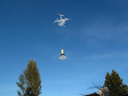
Quick comparison between the PA0RDT Mini-Whip and The RA0SMS Mini-Whip
I have found it very worthwhile to use toroidal 'choking' in the form of a Guanella balun simultaneously on all lines going in/out of my KiwiSDRs.
as shown in the bottom portion of the figure.
Like the situation so nicely described by G3TXQ's graphic, suitable cores need to be used, possibly several of them to cover the broad frequency range of the Kiwi. By winding equal turns in the same direction with each line on a single core, the effective current that can flow through the receiver is reduced by the "transformer action" of the cores. Current that would otherwise flow into and through the SDR creates common flux within the core that causes an opposite current to come out, thus pushing total current toward zero and effectively creating a much higher impedance than can be the case when each line has only a dedicated core.
From my experience, CM currents through the entire KiwiSDR structure produce IZ drop that appears across the effective ADC input, which is a complex function of PCB layout and conductivities - the "attenuator problem". For this reason, I believe, treating all lines as common mode lines, in addition of course to also eliminating differential noise across pairs of individual conductors of those lines, e.g. power line or inter-pair CAT5 noise, can be very effective in improving the KiwiSDR noise floor.
Glenn n6gn

-
KiwiSDR production status and availability
I tested Master Electronics by ordering only a single enclosure. The process went flawlessly and the enclosure arrived as promised after 8 days.
They seem to be fine.
Glenn n6gn

-
External GNSS-disciplined rubidium input?
I know very little about the TDoA algorithm but I suspect both @jks and @Christoph are correct. Between the limited bandwidth and especially ionospheric propagation, typical Kiwi clock imperfection probably does not become an issue.
For an appreciation of this, you are welcome to examine the phase of one of NIST's transmitters received via a visual line-of-sight 20km path and displayed on a Kiwi having a ~.1 ppb (1e-10) GPS-disciplined external clock:
and by a different 'stock' GPS-corrected Kiwi at the same distance and also not receiving via the ionosphere:
Then have a look at a time/frequency signal via the ionosphere, CHU on 14670 kHz
(3) N6GN CHU 14670
or if conditions don't permit, perhaps 7850 kHz
Whether or not the the phase wander from the standard Kiwi in (2) causes significantly extra error compared to the bandwidth and sample-length restrictions and ionospheric variations would need to be examined more closely but I rather doubt it. Thus, improving the Kiwi's local clock probably wouldn't make much difference in the TDoA accuracy or resolution.
I think this is the primary reason that long-distance HF standard frequency transmissions tend to be only useful to .1 ppm. 1e-7, or so. Even though as-transmitted error may be 1e-12 the ionospheric path length is varying too much, particularly near the MUF for better accuracy.


-
Help with local interference
Presuming I have the correct K7GFH-associated Kiwi, at 1450 UTC you really aren't doing too badly. While I do hear a mains-related family of QRN from LF half way into HF, the levels aren't that terrible. Using the 10 kHz AM detector to allow hearing it (the individual lines tend to correlate and 'pop out' much more than in a narrower SSB bandwidth, they are found to almost completely disappear by 10 MHz leaving the Kiwi -154 dBm noise floor. This is assuming that the calibration is still about -16 and thus close to correct and no significant gain/attenuation on the way to the antenna.
The largest MWBC signal is around -30 dBm but there's no other station close to cause too much worry and there's no indication of OV.

Even at VLF you are hearing many stations pretty well, HI and Australia included. There's line related noise but I've seen far worse on many other systems. You're hearing well on 160m with several stations showing a lot of SNR.
Because this family of QRN starts so low rather than as modulation superimposed on a family of SMPS rate beginning higher up, I tend to suspect that it is rectification noise getting either back into the mains wiring or ground currents.
Here's a crude analysis of a little IQ/10kHz done by Audacity:

It does have 'ragged' edges around full-wave rectification (120 Hz) which may be what's responsible. I can't account for these.
OTOH, maybe the problem you are asking about has chosen this time to be absent.

-
Quiet switch mode power supply (SMPS) for KiwiSDR
Getting rid of differential noise is fine, though the power management IC regulators in the Kiwi's BB is so good that this is seldom to never a problem, in my experience. (Try deliberately introducing differential noise and check the Kiwi's response. I haven't done this for a while but I think even 100 mV tends to be pretty invisible)
But just looking the schematic of this typical linear regulator and wondering ...
What would happen if we built a PS, either linear or SMPS and then added another series pass device in the 'GND' leg of the output to raise the impedance and reduce CM current? Against typical CM source/load impedances, would it significantly improve the situation in real circumstances?
It likely might not since typical total CM impedance may be in the 100's of ohms territory and well above the effective resistance of the series pass devices, but it wouldn't be difficult to try.

-
FT8 6m Autorun [fixed in v1.695]
I think the question was reasonable since it was "using down converters". For this reason using a frequency converter/extender such as the 0-2 GHz transverter I use here suggests the value of having many additional bands listed as options.
Amateurs have already made a great deal of use of narrow band modes above HF, particularly WSPR on 2m and shorter wavelengths.
6m FT8 is very active now in the Northern Hemisphere as we are in the midst of the sporadic E season. With the LO offset JKS has added, the KiwiSDR already natively supports all-modes on all-bands. Adding FT8 support and even all-extension support makes a lot of sense to me.
Why not support it all in a Kiwi?

-
Taming a switching supply?
Just 1:1 on small PCB, SMA male to Kiwi Completely isolated from SMA female to antenna feed line. This leaves only about 1 pF of common mode coupling between Kiwi and antenna line.
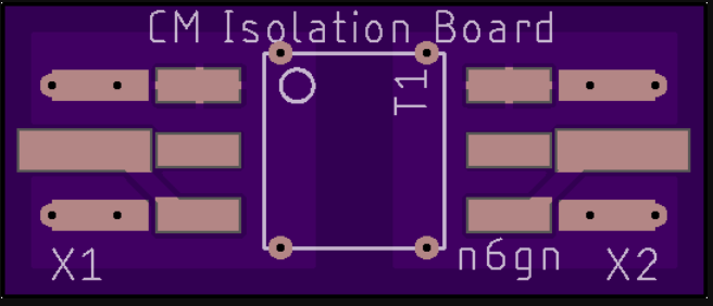
top side of board shown above, Center tap, if present T1-1T, is unused.
T1-1 from Mini-Circuits,
SMA edge connectors from eBay,
unzip & drop .brd file onto OSHPark.com. 3 boards postpaid in US in about 10 days, probably < US$5.

-
VHF downconverter recommendations?
I've not examined recent products from the Ukraine but I can not recommend the earlier transverters. Perhaps the receive converters are different/better.
How much interest would there be in the creation of a fast-switching block down-converter for the Kiwi? This would be something with a high side, say 3 GHz IF preceded by a [20 MHz] stepping LO that went from, 3-6 GHz, mixer and LPF?
The result would be an "all band" down-converter one [20 MHz] swath at a time such that the Kiwi could use any of it's capabilities over 0-3 GHz? NF and IMD could be good and no additional filtering would be necessary as long as out-of-band signals were kept tolerably low compared to a mixer's spec. +20 dBm TOI should be fairly easy. Of course, filtering could be added at the input, as for a band-limited converter of the type most often used.
It would seem to me that a Kiwi extension to use I2C to control the LO/receive_frequency should not be difficult. The goal would be fast switching so that multiple 20MHz chunks might be stitched together to create a wider spectrogram.
Glenn n6gn

-
Power-over-USB modifications for a KiwiSDR
I'm attaching a write-up of what has worked well for me to improve Kiwi noise performance by reducing common-mode current paths through the Kiwi.
For a stock, wired-LAN Kiwi it is very common for noise and coherent signal current on the LAN cable to find a path through the Kiwi PCB ground and out either the Power Supply return or, more often, via common mode current on the antenna feed attached to the SMA input. This kind of QRM/QRN is insidious because it may mostly show up when an antenna is attached causing the user to believe the problem is elsewhere.
By operating the Kiwi with an inexpensive WiFi router, powered from the Kiwi and connected by only a single micro_USB <==> USB-A cable, the common mode current paths which can cause this degradation can be eliminated.
Because of the success of this scheme in both improving performance of previously wired-LAN installations and also the possibility of building a completely isolated, portable Kiwi system to use as adiagnostic tool for improving Kiwi and general site performance, I'm offering this description.
Write me for more information or for the 3D printable file for the USB clamp described.
Glenn n6gn


