n6gn
About
- Username
- n6gn
- Joined
- Visits
- 4,513
- Last Active
- Roles
- Member
- Points
- 18
-
DIY MW Bandstop Filter PCB
I tried to attach a file to this posting, daughter1.2.brd, which if dropped onto OSHPark's PCB fabrication site and submitted should result in a small PCB that can be loaded with SMD parts to produce a MW bandstop filter for use with the KiwiSDR or other SDRs that might suffer from overload in the .6-1.6 MHz region. The forum wouldn't let me post a file of this type so after I send this I'll try to post it to a files section, if I can. If not, ask and I can email it to you directly.
As shown, this filter suppresses signals in this range 15-20 dB without significantly affecting the rest of signals within the SDR's range.The board can be fabricated at nominal cost, OSHPark provided me with 3 boards shipped postpaid (they advertize free shipping worldwide) for under US$4. To build it you'll need to obtain the L's, C's and R's and solder them and two coax connectors onto the PCB but parts are not special and can be ordered from Mouser, Digikey or your favorite supplier. I would suggest selecting 5% tolerance if possible but use what you can get. R's and C's are 0603 package and the L's are 1210. The inductors are standard values which should be commonly available and the nearest available capacitor values should be fine. If necessary you may parallel two capacitors to get near the value indicated on the schematic. If you can get within 5-10 % the filter should work approximately as shown. Don't worry about being too precise, the resonances are mostly lower Q and thus not terribly critical. Here's what it looks like after less than an hour's effort:

Either SMA or SMB connectors may be used and edge-mounted. These are no doubt the most expensive part of the filter so if you really want to be frugal you can simply solder coax directly to the board instead.
Even without careful parts value selection here's a good approximation of what you should end up with
You'll see that there is left unloaded one series RLC trap. I included this because I have a significant problem with an LF signal, WWVB at 60 kHz, overloading my KiwiSDR which the MW bandstop didn't address. The situation at your location will no doubt be different but you can easily add two or three parts and greatly reduce a single frequency if you do have a problem from a strong local like I did.
This is by no means the only selection of values that can work. You can use an Open Source circuit simulator such as QUCS to obtain different values from what I chose if you'd like different performance. My goal was to get a enough attenuation to keep the KiwiSDR out of overload and with fairly flat stop band so that it would be easy to arrive at a reasonable estimate of unfiltered signal strength by just adding a constant back in for any signal in the MW stop band. If your problem is other than MW, perhaps strong SW broadcast overload from one of the HF bands, you can generate new values but use the same board to make a different filter.
If I don't succeed in getting the .brd file posted, write me and I'll be happy to mail it to you. Similarly if you have questions ask and I'll do my best to answer them.
Glenn n6gn
Fort Collins, Colorado

-
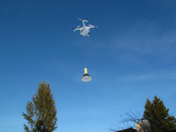
An antenna switch for the KiwiSDR
Here's a photograph in case you just want to see it but don't want to download the pdf


-
Washed out signal help
If you could plot it with the spectral display turned on, it might be easier to analyze the signal. The waterfall isn't nearly so good a tool for this.
-
OpenWebRX [using a transverter/down-converter with the Kiwi]
Oh, just realized that the WSPR extension is using the 10m entry for band so assumes that means 28.1246 carrier. 28.1246+.001529 audio comes out as shown. At least it's correct at the 1 Hz level but not right about band or MHz ! There's apparently no way to run on other bands, such as VHF/UHF, or non-standard WSPR frequencies with the extension.
-
OpenWebRX [using a transverter/down-converter with the Kiwi]
Until ~6 years ago when a few of us grew a significant base of VHF+ WSPRers, there weren't even 'standard' frequencies above 2m and virtually no activity. As more got on up there and discovered what a great tool WSPR was -contrary to what K1JT had expected since he had thought Doppler self-QRM would be prohibitive- and started discovering previously unrecognized propagation mechanisms such as aircraft scatter (ACS, good for 800-900 km day/night year-round) and wing-tip vortex (WTV)signals some worldwide frequencies for 70cm and 23 cm were adopted. I built a 70 cm multi-mode beacon that was placed at the KH6HME site on Maunba Loa which is now almost routinely copied on the mainland now 4100 km away on WSPR, JT9, JT65 and sometimes CW.
But I think the WSPRnet database does keep track of 'non standard' frequencies, e.g. the dual 80m WSPR bandplan that has frequency reported correctly while both segments are lumped into '80 m'. If one runs WSPR on 10 GHz (yes, it's been done) I think it becomes available on the database and map though I can't remember what 'band' it calls it. -
Ethernet filters
For $US50 DX Engineering shipped me a pair of filters and two short cables to allow inserting them in-line. But before actually trying them out, I had to at least take one apart to see what they were. Essentially these are back-back HALO HFJ11-1G46ERL Ethernet filters, RJ45 connectors with built-in current and voltage baluns
As you can see there is no DC connection between shields and there is the balance/symmetry of the transformer isolating shield and pair currents from appearing on the output lines. DXEngineering's page doesn't indicate what the test conditions were for their measurement showing > 20 dB CMRR across the HF bands. In use, the attenuation obtained will depend upon source and load impedances which aren't specified but were perhaps 50 ohms for their measurement. I'd expect typical long lines of CAT5 to show considerably higher impedance at some frequencies and so net reduction of CM current may not be nearly so great as their plot would indicate, at least not everywhere.
They indeed will not allow POE since one of the two baluns is flux-coupled and is essentially a HPF with no DC response.
From Martin's, G8JNJ's, schematic of the BB grounding it looks like these filters could potentially improve the noise floor for KiwiSDRs. If I'm reading it correctly, the CAT5 shield is connected to BB and enclosure grounds directly. Thus any CM current injected onto the CAT5 shield or lines and given a return path out the SMA isn't suppressed. As I've written before, I measured about 70 dB attenuation for this path - an isolated 0 dBm 50 ohm source placed across the SMA/LAN-end grounds resulted in about -70 dBm signal detected by the Kiwi. This implies to me that many of us may have our noise floors raised with spurious signals getting in by this mechanism. Since the ultimate floor of the Kiwi itself is about -157 dBm/1-Hz there's a lot sensitivity to see this kind of interference.
But the LAN cable is not the only way for CM currents to be injected, the PS and even GPS cable are other possibilities as well. And I haven't even tried the filters out here and so it's too soon to judge, just thought I'd pass along these details since I was thinking about it.
If you want to roll your own filter, Mouser sells them in singles for US$12.50 so DX Engineering is giving them to us mounted on a board in a little molded housing along with a cable for the price you'd have to pay for 4 connectors alone. However, if you're willing to make several yourself, at quantity of 25 they drop to US$8.57/per and getting the finished product from DXEngineering isn't such a good deal. I wonder if we'd see any improvement in a KiwiSDR if the RJ45 connector were replaced with one of these.
-
Ethernet filters
For $US50 DX Engineering shipped me a pair of filters and two short cables to allow inserting them in-line. But before actually trying them out, I had to at least take one apart to see what they were. Essentially these are back-back HALO HFJ11-1G46ERL Ethernet filters, RJ45 connectors with built-in current and voltage baluns
As you can see there is no DC connection between shields and there is the balance/symmetry of the transformer isolating shield and pair currents from appearing on the output lines. DXEngineering's page doesn't indicate what the test conditions were for their measurement showing > 20 dB CMRR across the HF bands. In use, the attenuation obtained will depend upon source and load impedances which aren't specified but were perhaps 50 ohms for their measurement. I'd expect typical long lines of CAT5 to show considerably higher impedance at some frequencies and so net reduction of CM current may not be nearly so great as their plot would indicate, at least not everywhere.
They indeed will not allow POE since one of the two baluns is flux-coupled and is essentially a HPF with no DC response.
From Martin's, G8JNJ's, schematic of the BB grounding it looks like these filters could potentially improve the noise floor for KiwiSDRs. If I'm reading it correctly, the CAT5 shield is connected to BB and enclosure grounds directly. Thus any CM current injected onto the CAT5 shield or lines and given a return path out the SMA isn't suppressed. As I've written before, I measured about 70 dB attenuation for this path - an isolated 0 dBm 50 ohm source placed across the SMA/LAN-end grounds resulted in about -70 dBm signal detected by the Kiwi. This implies to me that many of us may have our noise floors raised with spurious signals getting in by this mechanism. Since the ultimate floor of the Kiwi itself is about -157 dBm/1-Hz there's a lot sensitivity to see this kind of interference.
But the LAN cable is not the only way for CM currents to be injected, the PS and even GPS cable are other possibilities as well. And I haven't even tried the filters out here and so it's too soon to judge, just thought I'd pass along these details since I was thinking about it.
If you want to roll your own filter, Mouser sells them in singles for US$12.50 so DX Engineering is giving them to us mounted on a board in a little molded housing along with a cable for the price you'd have to pay for 4 connectors alone. However, if you're willing to make several yourself, at quantity of 25 they drop to US$8.57/per and getting the finished product from DXEngineering isn't such a good deal. I wonder if we'd see any improvement in a KiwiSDR if the RJ45 connector were replaced with one of these. -
An antenna switch for the KiwiSDR
Attached is a pdf that describes my current efforts to design and build an antenna switch for the KiwiSDR and the reason behind them. I'm posting it in case it may be of interest or useful to KiwiSDR owners, not because I'm interested in manufacturing or providing one - I'm not.
This is subject to revision...
Glenn n6gn


-
An antenna switch for the KiwiSDR
Attached is a pdf that describes my current efforts to design and build an antenna switch for the KiwiSDR and the reason behind them. I'm posting it in case it may be of interest or useful to KiwiSDR owners, not because I'm interested in manufacturing or providing one - I'm not.
This is subject to revision...
Glenn n6gn
-
An antenna switch for the KiwiSDR
Here's a photograph in case you just want to see it but don't want to download the pdf


