n6gn
About
- Username
- n6gn
- Joined
- Visits
- 4,515
- Last Active
- Roles
- Member
- Points
- 18
-
Seeed Metal case and GPIO connector
Martin,
The mechanism I have observed is in addition to these, looks something like this:
without perfect balance (infinite CM impedance) at the far end of the (shielded) LAN or PS cable there is *still* ingress at the ADC.
-
Seeed Metal case and GPIO connector
Martin,
Thanks for documenting this. From my observations, mainly at HF, the 20-30 MHz noise that is endemic with Kiwis has a vector into the kiwi via CM noise on the LAN connection/lines. I think this is what you were addressing with the CAT5 shield, though it is still possible to get TEM ==> CM conversion on a long cable even with shielding, depending how it is configured. Current injected on the far-end shield can still end up inside the box.
Often this QRN manifests as a family of ~60 kHz separation lines in the 20-30 MHz region. Rob, AI6VN has had good success in mitigating these, without additional enclosure shielding, through use of a USB/WiFi dongle which bypasses the wired LAN connection and attendant spurious energy. Perhaps he will post some documentation of that as well.
Best,
Glenn n6gn
-
Anyone using the DX Engineering RF-PRO-1B Active Mag Loop Antenna?
The splash image on http://n6gn.no-ip.org:8073/ has a schematic of a MW band stop that surpresses MW BCB by about 20 dB and allows for one additional notch elsewhere. This may protect a Kiwi from OV while still allowing only slightly reduced access to stations in MW and good access elsewhere. It can be fabricated from inexpensive SMD components.
-
Possible to pass arguments to an extension using kiwirecorder?
While " /sys/class/gpio/gpioNN/value" did allow toggling the lines, it seems that it is toggling more than one. I haven't studied the class to understand it and there may be a way around this, however, Gwyn G3ZIL, kindly pointed me to another way that seems to do exactly what I want even more directly. It is:
rsh root@[kiwi IP address] "/root/extensions/ant_switch/frontend/ant-switch-frontend N;" 2>/dev/null
where N is the Antenna N selection desired and 2>/dev/null throws away the return text from the BB resulting from the remote shell call. I expect using this method requires compiling the ant_switch extension into the Kiwi but that is well documented and only takes a few minutes.
This seems to work precisely as hoped and allows setting the GPIO lines of the ant_extension one-at-a-time. I measured 600 ms/setting across my local network.
If someone simply wants a few control lines to use to programatically control an external device on a kiwi - whether an antenna switch or something else - this seems to be a quick, easy and effective way to do it remotely.
I've only tested from a remote computer running Ubuntu Linux but perhaps someone more familiar with Windows can provide an equivalent method for that OS.
See https://github.com/OH1KK/KiwiSDR-antenna-switch-extension/blob/master/docs/antenna-schedules-using-crontab.txt
for automating this with crontab from the kiwi itself.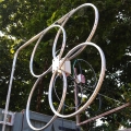
-
MIni Enhancement on the new S meter
Darn, file attach didn't work. Here it is in-line:
#!/bin/bash
### This bash script to sweep a kiwi and report S-meter reading
### steps through the set frequencies
### and stores the results, timestamped, in a file whose name is passed as an argument when calling the script
### Dependencies: Needs kiwiclient directory with kiwirecorder.py
### Version 1.0 May 2019 Script from Gwyn Griffiths G3ZIL hacked for WB7ABP by N6GN
### Version 1.1 throw away initial measurement after frequency (or other?) change. It's bogus. Remove delays
#
#if [$# lt 1]
# then
# echo "no argument"
#fi
#
#3echo "This script needs a single argument, the output file name with a csv extension, e.g. test_22_May_2019.csv"
VERBOSITY=1 # set 1 for test mode, otherwise 0
# say where kiwirecorder is on this host
KR='python /home/ge/kr_test/kiwiclient-master/kiwirecorder.py'
# set the start, stop and increments for the test frequencies, could also be an array e.g. for wspr bands, revisit
START=12000
INC=50
STOP=16000
# quiet ? spots
LIST="60 400 560 600 760 1060 1360 2500 5000 10000 15000 20000 25000 28000 29950"
#LIST={$START..$STOP..$INC}
# one frequency point with 2 averages takes about 1 sec, 10 averages ~2 sec and 100 takes ~20 seconds.
AVERAGES=10
# target KiwiSDR
HOST=10.0.0.77
PORT=8074
# write header to the csv file, with names on one line, units on the other
DATE=`date --utc "+%Y/%m/%d %H:%M"`
echo "Measuring, $HOST, $PORT, on, $DATE" >> $1
echo " Frequency, S Meter" >> $1
echo " kHz, dBm " >> $1
#for i in `seq $START $INC $STOP`
for i in $LIST
do
echo "acquire data for $i kHz"
# set to 10kHz bandwidth
OFF=`$KR -s $HOST -p $PORT -f $i m iq -L -5000 -H 5000 --s-meter 1` # discard, first reading is bogus !!!!
OFF=`$KR -s $HOST -p $PORT -f $i m iq -L -5000 -H 5000 --s-meter $AVERAGES`
# strip off the leading "RSSI:"
Smeter=$(awk -F: '$0=$2' <<<"$OFF")
if [ $VERBOSITY == "1" ]; then
echo "Level was $Smeter dBm"
fi
#
# write data to the file
# get the date and time in UTC
# DATE=`date --utc "+%Y/%m/%d %H:%M"`
# echo "$DATE,$i,$Smeter" >> $1
echo "$i,$Smeter" >> $1
done
echo "Finished sweep"
echo $LIST
-
MIni Enhancement on the new S meter
While it's being tweaked, an option for markers out to 1/hour or less frequent would be great.
It's fascinating to watch thunderstorm level and perhaps even galactic center noise floors! -
Distortion & Noise Measurement of a new KiwiSDR, June 2018
I recently received a KiwiSDR from Mass Drop and made some measurements of distortion and noise of the unit. These measurements and their results are detailed in the attached file.
Glenn n6gn


-
Distortion & Noise Measurement of a new KiwiSDR, June 2018
I recently received a KiwiSDR from Mass Drop and made some measurements of distortion and noise of the unit. These measurements and their results are detailed in the attached file.
Glenn n6gn -
An antenna switch for the KiwiSDR
Attached is a pdf that describes my current efforts to design and build an antenna switch for the KiwiSDR and the reason behind them. I'm posting it in case it may be of interest or useful to KiwiSDR owners, not because I'm interested in manufacturing or providing one - I'm not.
This is subject to revision...
Glenn n6gn

-
DIY MW Bandstop Filter PCB
I tried to attach a file to this posting, daughter1.2.brd, which if dropped onto OSHPark's PCB fabrication site and submitted should result in a small PCB that can be loaded with SMD parts to produce a MW bandstop filter for use with the KiwiSDR or other SDRs that might suffer from overload in the .6-1.6 MHz region. The forum wouldn't let me post a file of this type so after I send this I'll try to post it to a files section, if I can. If not, ask and I can email it to you directly.
As shown, this filter suppresses signals in this range 15-20 dB without significantly affecting the rest of signals within the SDR's range.The board can be fabricated at nominal cost, OSHPark provided me with 3 boards shipped postpaid (they advertize free shipping worldwide) for under US$4. To build it you'll need to obtain the L's, C's and R's and solder them and two coax connectors onto the PCB but parts are not special and can be ordered from Mouser, Digikey or your favorite supplier. I would suggest selecting 5% tolerance if possible but use what you can get. R's and C's are 0603 package and the L's are 1210. The inductors are standard values which should be commonly available and the nearest available capacitor values should be fine. If necessary you may parallel two capacitors to get near the value indicated on the schematic. If you can get within 5-10 % the filter should work approximately as shown. Don't worry about being too precise, the resonances are mostly lower Q and thus not terribly critical. Here's what it looks like after less than an hour's effort:

Either SMA or SMB connectors may be used and edge-mounted. These are no doubt the most expensive part of the filter so if you really want to be frugal you can simply solder coax directly to the board instead.
Even without careful parts value selection here's a good approximation of what you should end up with
You'll see that there is left unloaded one series RLC trap. I included this because I have a significant problem with an LF signal, WWVB at 60 kHz, overloading my KiwiSDR which the MW bandstop didn't address. The situation at your location will no doubt be different but you can easily add two or three parts and greatly reduce a single frequency if you do have a problem from a strong local like I did.
This is by no means the only selection of values that can work. You can use an Open Source circuit simulator such as QUCS to obtain different values from what I chose if you'd like different performance. My goal was to get a enough attenuation to keep the KiwiSDR out of overload and with fairly flat stop band so that it would be easy to arrive at a reasonable estimate of unfiltered signal strength by just adding a constant back in for any signal in the MW stop band. If your problem is other than MW, perhaps strong SW broadcast overload from one of the HF bands, you can generate new values but use the same board to make a different filter.
If I don't succeed in getting the .brd file posted, write me and I'll be happy to mail it to you. Similarly if you have questions ask and I'll do my best to answer them.
Glenn n6gn
Fort Collins, Colorado


