n6gn
About
- Username
- n6gn
- Joined
- Visits
- 5,484
- Last Active
- Roles
- Member
- Points
- 31
-
GPS input
Here's an 8-way one for around US$30 if you order two.

-
HT004a / LNA / Anyone used one?
Martin
The differentiating point I was trying to make is about 'local environment' You wrote that further improvement can only be improved by using a better antenna. I was trying to make clear that there can be and usually are multiple causes for increased noise in a local environment. Some of these are actually arriving by way of the perceived antenna due to near-field coupling but a second type come in after that in the form of CM currents and other kinds of systemic ingress.
A preamplifier at the antenna may actually help reduce this second type and create an overall improvement. This improvement would not be due to an antenna change, at least not what was thought to be the antenna. In fact, in that case "the antenna was not the antenna" ! The system had multiple but separable sources of unwanted ingress.
It is a widely held belief that the shield on single ended/coaxial cable prevents ingress from occurring there. This is only true for TEM systems where there is zero common mode current, unwanted current flowing on the outside of the coax. When such current does flow on the outside, then imbalance at either end converts some of that current to differential current in the desired TEM component.
Because the systems we use often deal with such small levels - down near the thermal noise limit of KTB, it can require far more system balance to sufficiently reject unwanted currents than is achievable with passive hardware. So-called 'broadband baluns' are often only able to achieve 20-30 dB of balance at best. This can be many ten's of dB less than is necessary to force the currents due to unwanted conversion below the incoming noise floor.
Unwanted current traveling through the groundplane of the KiwiSDR, for example, is converted "only" 80 dB down to current through the center conductor of the coax and injected into the ~50 ohm input impedance of the preamp. That CM ==> differential conversion can and does easily damage reception SNR, often without the knowledge of the user who may think "I hooked up the coax and the noise floor came up, I guess it came in from my antenna" when in fact the majority of it did not.
Our goal is to transfer the DX (far-field) propagated SNR present within the radiation resistance of our antennas to the detector of our receiving system. Without understanding and identifying the multiple mechanisms by which this can be degraded and which are active in a particular system, there really are no simple answers to improving a [poorly behaving] receiving system. As you suggest, blindly adding a preamplifier may make no improvement at all and may only make things worse due to IMD, internal noise or additional conversion from CM ==> differential QRN.
Without understanding that "our antennas are not what we may think they are" and "coax shield does not prevent unwanted ingress" the techniques we might use to improve our results likely will not deliver the improvement that is possible.

-
VDSL2 interference what options have I got
If you use a broadband display, particularly one with min/max hold you can appreciate where the QRM is by the ham-band notch depths as well as how much it is hurting your SNR.
Here is capture of reverse channel, user ==> Internet, Internet-over-coax, QRM leaking from a neighbor of N6GN received on an RX888 and recorded with ka9q-web from ka9q-radio. Some of the ham band notches are IDed. The depth of the notch indicates how badly the SNR is being hurt by this interference.
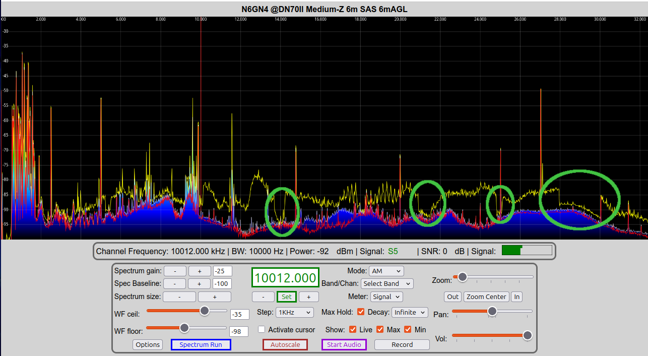
This is being received by a 6m dipole SAS which has quite flat field response over these marked frequency range.
Because of the notches, ham band performance isn't being hurt but SWL and other listening at other frequency certainly is.

-
LZ1AQ Active Amp and a "Fat" Lazy loop - Dual Opposing Loops.
Don't confuse lower levels with lower SNR, which can sometimes happen. A properly operating loop should have ultimate performance very similar to a similar sized dipole probe, at least up through mid HF, modulo antenna pattern in az&el which can favor one or the other depending upon what you consider 'better'.
As LZ1AQ has written, making a small lowZ system reach propagated noise limits in the quietest locations may be impossible at the high end using components known-to-mankind as it is for small dipoles. But in general if/when all the other system noise ingress, noise floor, and IMD are pushed below the propagated noise produced within either antenna's radiation resistance the limits are very similar.

-
Uncommanded 26 dB attenuation, SMA connector tightening
I worked in an HP microwave lab and as I remember the production line spec for torque was surprisingly low, only 7 inch-pounds. That was with quality connectors on the highest quality vector network analyzers as well as on swept signal sources. As time went on other connector types good to above 18 GHz came to the fore but I don't think they were tightened more.
As Martin suggests, it's very easy to over-tighten these beyond that specification thinking it will make things better. It probably will only make things worse.
Glenn n6gn

-
Quiet switch mode power supply (SMPS) for KiwiSDR
Getting rid of differential noise is fine, though the power management IC regulators in the Kiwi's BB is so good that this is seldom to never a problem, in my experience. (Try deliberately introducing differential noise and check the Kiwi's response. I haven't done this for a while but I think even 100 mV tends to be pretty invisible)
But just looking the schematic of this typical linear regulator and wondering ...
What would happen if we built a PS, either linear or SMPS and then added another series pass device in the 'GND' leg of the output to raise the impedance and reduce CM current? Against typical CM source/load impedances, would it significantly improve the situation in real circumstances?
It likely might not since typical total CM impedance may be in the 100's of ohms territory and well above the effective resistance of the series pass devices, but it wouldn't be difficult to try.

-
FT8 6m Autorun [fixed in v1.695]
I think the question was reasonable since it was "using down converters". For this reason using a frequency converter/extender such as the 0-2 GHz transverter I use here suggests the value of having many additional bands listed as options.
Amateurs have already made a great deal of use of narrow band modes above HF, particularly WSPR on 2m and shorter wavelengths.
6m FT8 is very active now in the Northern Hemisphere as we are in the midst of the sporadic E season. With the LO offset JKS has added, the KiwiSDR already natively supports all-modes on all-bands. Adding FT8 support and even all-extension support makes a lot of sense to me.
Why not support it all in a Kiwi?

-
Taming a switching supply?
Just 1:1 on small PCB, SMA male to Kiwi Completely isolated from SMA female to antenna feed line. This leaves only about 1 pF of common mode coupling between Kiwi and antenna line.
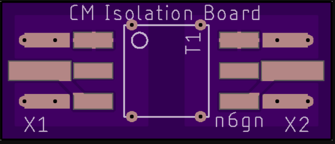
top side of board shown above, Center tap, if present T1-1T, is unused.
T1-1 from Mini-Circuits,
SMA edge connectors from eBay,
unzip & drop .brd file onto OSHPark.com. 3 boards postpaid in US in about 10 days, probably < US$5.

-
VHF downconverter recommendations?
I've not examined recent products from the Ukraine but I can not recommend the earlier transverters. Perhaps the receive converters are different/better.
How much interest would there be in the creation of a fast-switching block down-converter for the Kiwi? This would be something with a high side, say 3 GHz IF preceded by a [20 MHz] stepping LO that went from, 3-6 GHz, mixer and LPF?
The result would be an "all band" down-converter one [20 MHz] swath at a time such that the Kiwi could use any of it's capabilities over 0-3 GHz? NF and IMD could be good and no additional filtering would be necessary as long as out-of-band signals were kept tolerably low compared to a mixer's spec. +20 dBm TOI should be fairly easy. Of course, filtering could be added at the input, as for a band-limited converter of the type most often used.
It would seem to me that a Kiwi extension to use I2C to control the LO/receive_frequency should not be difficult. The goal would be fast switching so that multiple 20MHz chunks might be stitched together to create a wider spectrogram.
Glenn n6gn

-
Power-over-USB modifications for a KiwiSDR
I'm attaching a write-up of what has worked well for me to improve Kiwi noise performance by reducing common-mode current paths through the Kiwi.
For a stock, wired-LAN Kiwi it is very common for noise and coherent signal current on the LAN cable to find a path through the Kiwi PCB ground and out either the Power Supply return or, more often, via common mode current on the antenna feed attached to the SMA input. This kind of QRM/QRN is insidious because it may mostly show up when an antenna is attached causing the user to believe the problem is elsewhere.
By operating the Kiwi with an inexpensive WiFi router, powered from the Kiwi and connected by only a single micro_USB <==> USB-A cable, the common mode current paths which can cause this degradation can be eliminated.
Because of the success of this scheme in both improving performance of previously wired-LAN installations and also the possibility of building a completely isolated, portable Kiwi system to use as adiagnostic tool for improving Kiwi and general site performance, I'm offering this description.
Write me for more information or for the 3D printable file for the USB clamp described.
Glenn n6gn


