The KiwiSDR 2 online store is open for orders! Please visit kiwisdr.nz
Please visit kiwisdr.com (documentation) and kiwisdr.nz (online store)
Seeed Metal case and GPIO connector

Hi All,
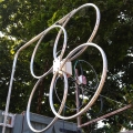
Just some brief notes regarding the installation of a 15 way D connector on the Seeed metal case in order to bring out the GPIO port for use with an antenna switch.
The ventilation slot cuts out very easily and only required a small amount of filing in order to make the connector shell fit.
First the pinout I used

End view of case

Top view of connector

Wiring to GPIO ports

Side view

Hope this is of some use to others.
Regards,
Martin - G8JNJ
Just some brief notes regarding the installation of a 15 way D connector on the Seeed metal case in order to bring out the GPIO port for use with an antenna switch.
The ventilation slot cuts out very easily and only required a small amount of filing in order to make the connector shell fit.
First the pinout I used
End view of case
Top view of connector
Wiring to GPIO ports
Side view
Hope this is of some use to others.
Regards,
Martin - G8JNJ


Comments
If some sort of serial/parallel data was to be carried (that is, something that would be impeded by R/C filtering) then I would, at least, put some sort of sacrificial buffer circuit in between the bare GPIO and the outside world.
73,
Clint
KA7OEI
Agreed, it's probably not best practice and it's sensible to include some resistors and filter caps.
In my case the switching unit is mounted adjacent to the KiWi and is connected by a short length of screened cable, so I'm prepared to risk it.
Regards,
Martin - G8JNJ
Terry G0EZY
I should have made this point in the posting.
The connector is simply to bring out the GPIO pins.
Some sort of interface circuit is still required to drive any external relays etc.
I use transistor drivers with about 100K from the GPIO pin to the base of an NPN switching transistor.
Regards,
Martin - G8JNJ
Yes full understood. The WJ antenna switches have built-in logic-level drivers but I'll use a buffer interface for belt & braces ..!
73 Terry
Nick W1NJC
I would still be tempted to put a series resistor in-line with the logic input pins (unless the switches already have some) as Clint has already suggested.
The GPIO pins can only provide a small amount of current and the danger is that if the DowKey RF switches/relays loose their supply, they may have internal protection diodes that will attempt to draw current from the input.
From the AM3359x datasheet rev. F Table 2-7 http://www.ti.com/product/am3359
The max current source capability is 6mA for all GPIO pins EXCEPT
gpio0[7,12,13,14,15,18,19,20]
gpio1[8,9,10,11]
gpio3[5,6,13]
which are 4mA max.
Of the GPIO signals brought out to P8 and P9 headers, all are 6mA max EXCEPT
P9_19 gpio0[13]
P9_20 gpio0[12]
P9_24 gpio0[15]
P9_26 gpio0[14]
P9_41 gpio0[20]
P9_42 gpio0[7]
which are 4mA max.
Regards,
Martin - G8JNJ
Thanks,
Nick
W1NJC
Glenn n6gn
I've had some issues with radiated noise from a KiWi that I installed on a shared site. The main issues were that it was interfering with of VHF satellite reception and degrading the GPS performance of another system in the same room.
The KiWi was installed in the Seeed metal case, and I had fitted ferrites to the cables.
As I'm currently building up a KiWi for installation at another site, I thought that it would be a good idea to see if I could further reduce the level of emissions from a KiWi fitted in the Seeed case.
In order to do this I used an EMC H-Probe consisting of a 1"diameter screened loop connected to a spectrum analyser, in order to see what the level of emissions looked like and where they were escaping from the case.
The majority of the noise was leaking out through the holes in the ends of the case and also via the additional interconnecting cables I had fitted to bring out the GPIO ports for antenna switching.
This shows the general level of radiation from a KiWi without a case, with the Seeed metal case and with the Seeed case and additional modifications. Note that the measurements were made without the external GPIO cable connected.
The next shot shows the difference between the Seeed metal case and with the Seeed case and additional modifications in more detail.
As you can see the biggest difference is achieved by fitting the metal case, and I would definitely recommend doing this if you are still using the plastic frame supplied with the KiWi.
However there is still a fairly significant amount of radiated noise throughout the whole spectrum, especially in the VHF / UHF / Microwave range, and the only way to cure this is to close up the holes in the box.
As I didn't want to restrict airflow and ventilation I used some very fine woven brass mesh that I previously bought for antenna construction.
I added a section of mesh at each end of the box and sandwiched it between the end plates and the box sides, having first cutout suitable holes for the connectors I still wished to use.
Note that I had to solder short brass sheet straps between the Ethernet port metal socket surround and the mesh and also the -ve of the DC input connector where it enters the board (prior to the common mode choke on the board) in order to reduce the level of radiated noise from the external screened CAT5 Ethernet cable and DC power cable. There already was physical / electrical contact between the mesh and Ethernet connector, but I noticed that the screening effectiveness varied as I flexed the cable, and I didn't want to risk problems on-site at a later date if the mesh tarnished or developed an oxide layer.
Here are a couple of external views, showing the wire mesh with the case closed.
Once I had done this work I still had some noise from the GPIO port, so I added some 0.1uF decoupling capacitors and some 1/8th watt 1K Ohm resistors in series with the wires from the KiWI GPIO pins (not the 0v ground return) and the decoupled pins of the output connector. This also provided some short circuit protection, as previously suggested as best practice earlier in this thread.
After doing all of this work, the level of emissions are now minimal, and the ambient level of noise in my workshop is higher than the majority of noise produced by the KiWi, even though the close field probe is right next to the case. There is still a bit of radiation along the seams between the top and bottom case halves, but this is very low level, and if necessary can be further reduced by running self adhesive aluminium (ducting) tape over the seams.
One other interesting observation is that before fitting the mesh and additional earth bonding strap, I didn't find that using screened Ethernet cable made much difference to the level of noise radiated around 20MHz. However after performing the modification it's really noticeable that using screened cable makes a big difference.
Overall I think the additional mods are worth doing, especially if you are bringing the GPIO pins out of the box. But if you are already housing your KiWi in a diecast box with suitable cable bonding, then you are probably already experiencing most of the benefits I have observed.
Regards,
Martin - G8JNJ
> are the PSU linear?
>
No, they are heavily modified switched mode units and are electrically / RF quiet. I selected the most quiet units from my pile of switchers, and then added extra filter components and screening foil inside the plastic cases. I now can't detect any RF noise above ambient levels on the PSU cables or by sniffing around their cases
The ferrites you see in the first picture are really precautionary only and help prevent common mode electrical noise that is carried on the mains cabling (safety ground connection) from entering the rest of the board.
Regards,
Martin - G8JNJ
I thought the RF connectors needed to be isolated from the case, it looks like this is unnecessary. I assume the brass screen could be mounted on the outside and have the same effect. Although not looking as nice, I imagine the end plates could be fabricated from screen which would also allow better airflow.
>I assume the brass screen could be mounted on the outside and have the same effect.
>
There is a problem in that the brass mesh has to have a good electrical connection to the end plates and the rest of the case. This is achieved by sandwiching it between the two surfaces.
The better option would probably be to make new end plates with many small ventilation holes instead of long slots.
The usual rule of thumb is that holes or gaps should be less than 1/10th of a wavelength diameter at the highest frequency of interest. However if you have cables or other items running very close to the holes, then RF can still be induced into the cabling and re-radiated.
This is important for me as I'm trying to get rid of the interference at VHF frequencies and above. But if you look at the spectrum analyser plots it also improves the HF frequencies (20-30MHz) by about 10dB, so it does have an overall impact.
As an example with a smaller RF 'sniffer' probe I can run it along the seam between the top and bottom case halves and see a peak in levels at the edges, then a drop and other peak in the middle then another drop and finally another peak at the other case edge. I think this is because the long seam has a resonance at a UHF frequency and is acting as a slot antenna.
(Edited to add correction) Interestingly the side of the case near to the RF connector is about 10dB worse than the other side, probably due to the proximity the seam to the interboard connector and PCB's on that side. The seam is lower down on the GPS connector side and as a result is further away from noise sources.
Regards,
Martin - G8JNJ
Thanks for documenting this. From my observations, mainly at HF, the 20-30 MHz noise that is endemic with Kiwis has a vector into the kiwi via CM noise on the LAN connection/lines. I think this is what you were addressing with the CAT5 shield, though it is still possible to get TEM ==> CM conversion on a long cable even with shielding, depending how it is configured. Current injected on the far-end shield can still end up inside the box.
Often this QRN manifests as a family of ~60 kHz separation lines in the 20-30 MHz region. Rob, AI6VN has had good success in mitigating these, without additional enclosure shielding, through use of a USB/WiFi dongle which bypasses the wired LAN connection and attendant spurious energy. Perhaps he will post some documentation of that as well.
Best,
Glenn n6gn
>Rob, AI6VN has had good success in mitigating these, without additional enclosure shielding, through use of a USB/WiFi dongle which >bypasses the wired LAN connection and attendant spurious energy.
>
Hi Glen,
I 100% agree, I think getting rid of the wired Ethernet connection is the way to go. It's very problematic and introduces a lot of unwanted noise.
I'll probably implement this once there is a consensus regarding an 'approved' set of hardware and a suitable set of step by step documentation that I'm able to follow, as that sort of thing isn't really my forte. :-(
The D-Link Thumbnail USB WiFi dongle looks like the best contender at the moment.
Regards,
Martin - G8JNJ
I don't entirely rule out understanding the CM mechanism from LAN to ADC better and knocking it down another 20 dB but the LAN balance really isn't too bad with the hardware we have so getting rid of the wired LAN current certainly may be the easiest and most sure-fire way to quench it.
I think Rob has gone through several different USB/WiFI adaptor dongles - not all successfully - and has a couple that are relatively easy to use along with a set of instructions. I think that of the two the bargain was a USD$2 adaptor (from ebay) that was at end-of-life but that another for US$17 also worked well. Maybe he'll provide those details when he next has opportunity.
Glenn n6gn
https://www.amazon.com/Woremor-WMF200-Magnetic-shielding-Radiation/dp/B01HDL0M8S/ref=pd_sbs_328_4/141-4464432-6544547?_encoding=UTF8&pd_rd_i=B01HDL0M8S&pd_rd_r=4c8a176a-602b-4cbd-baf1-6f1640630a45&pd_rd_w=9w7J8&pd_rd_wg=ZuLeI&pf_rd_p=1c11b7ff-9ffb-4ba6-8036-be1b0afa79bb&pf_rd_r=FWYQWQF0P2DKJGEVACSP&psc=1&refRID=FWYQWQF0P2DKJGEVACSP
>I wonder if a case made of mu-metal would improve things
>
I suspect by only a very small amount.
Mu-metal tends to be used as a form of magnetic screening at low (audio) frequencies and is typically used for items such as microphone transformers and guitar pickups to reduce the pickup of mains hum from power transformers.
The KiWi is not emitting (much) noise by means of a magnetic induction (H-Field), so almost any conductive screening material (with adequate skin depth) should be able to contain the electric field (E-Field) noise.
Regards,
Martin - G8JNJ
Coupling at VHF/UHF is somewhat another matter though as the slots in the end caps are getting pretty large in terms of a wavelength so that is yet another ingress/egress avenue, though probably not one that shows up directly in the receiver's output but more likely as VHF or UHF/GPS radiated interference.
With ~4 decades of frequency coverage there are certainly different ways interferers can show up - even more than this if you count GPS - so driving all mechanisms out of sight seems pretty much a career. The bad news is that we have these signals and noise to contend with but the good news is that we can see far enough down to have to worry about them.
Glenn n6gn
I think for me the main issue is that the interconnecting cables are not all bonded to the case at the point of entry with low impedance connections.
So RF currents will flow via separate routes across the PCB's and find various ways of interacting with the circuit components as a result.
By bonding at the point of entry, you preserve the screen around the whole assembly and don't provide an opportunity for differentials to be setup between cables.
Most of the cables connected to the KiWi are relatively straightforward and can easily be filtered and screened. However the Ethernet port is an exception, as this has its own filter network and balancing transformers contained within the actual PCB mounted Ethernet socket. The main issue with this, as far as I can tell, is that the components have been chosen to help comply with worldwide EMC regulations, most of which only apply above 30MHz. So their performance below this frequency, where we are mainly interested, can be somewhat hit and miss. If we can do away with the wired Ethernet connection, by using a USB WiFi dongle, then a lot of these problems simply disappear.
Here are some notes I copied from Keith Amstrong's very comprehensive notes on EMC compliance. They are free but you need to register your email address to be able to read them. They cover just about every aspect of EMC design, and you would have to complete a degree level training course, costing several thousands of pounds (or dollars) to have access to similar information.
The 'Past Articles' section is probably the quickest read, but it's worth taking a good look around if you have the time.
http://compliance-club.com/keitharmstrong.aspx
2.6.2 How shielded interconnections work
When a shield interacts with an EM-field, currents flow in the shield. Skin Effect makes RF currents travel on the surface of a shield, with current density diminishing with depth into the shields metal by 36% for every skin depth. The higher the frequency, or the more conductive the metal of the shield, the smaller is the skin depth. For good shielding effectiveness the shield should have many skin depths of thickness at the lowest frequency to be shielded. Skin effect is not described further here, but a useful reference is [8]. Figure 2P shows that providing we achieve our 360o shield coverage and 360o electrical bonding at shield joints, and have enough thickness in our shields metal given the frequency, the skin effect tends to force the external surface currents to flow on the outside of the shield, and the internal surface currents on the inside.
4.3.9 Near-field leakages through apertures
So far we have assumed that the source was so far away that its EM radiation was plane waves, i.e. the shield was in the far-field of the radiating source - the usual situation when trying to protect electronics from external RF sources (to improve immunity).
But when using shielding to reduce emissions from a product, the shield is usually in the near-field of the source - and the SE from plane wave assumptions can be very wrong indeed, especially at lower frequencies. The closer the RF source is to the apertures, the worse the SE. Very significant amounts of leakage can occur, especially at low frequencies, even through arrays of very small apertures that have very low SE for plane (far-field) waves, see [17] for more detail.
Figure 4R sketches the E and H fields around an aperture, indicating that they are associated with regions of reduced SE, where it would be inadvisable to locate noisy or sensitive components or conductors.
This is how to make 'sniffer' probes that you can use with your KiWi to track down interference sources.
1.1 Close-field probes
Close-field (also called 'near-field') magnetic and electric field probes are low-cost to buy and very quick and easy to make. They are commonly used in development, diagnostic and QA work. There are many articles and papers describing how to make various versions of such probes, and most EMC test equipment manufacturers also sell their own versions of them. Figure 1 shows the three main constructions for magnetic field probes.
Near-field probes should always use 50R cables, and the input impedance of the RF measuring instrument they are connected to should also be 50R. Where the test instrument does not have a 50R input option, use its high-impedance input but fit a 50R BNC terminator at the instrument end of the probe's cable, for example using a BNC 'Tee' piece or through-line terminator. The 50R termination helps stop resonances in the probe cable which would otherwise occur when its length exceeds one-tenth of the wavelength of the highest frequency of interest (e.g. 50R termination is necessary for cables longer than 300mm for a highest frequency of only 50MHz - remembering that the wavelength for a signal in a cable is roughly half that of an electromagnetic wave in free space).
Figure 2 shows a standard electric field probe design, and also a 'pin probe'. The pin probe is a voltage probe which makes contact to the circuit or metalwork of interest via a 10pF capacitor, and it picks up the common-mode (CM) voltage as well as the signal voltage. CM voltage is a big contributor to radiated emissions. Magnetic field probes are shielded so that they don't pick up electric fields, which can sometimes leave them 'blind' to an important source of emissions. Usually, for small products, it is the CM currents leaking out via cables that cause most of the radiated emissions, but sometimes it is the electric field caused by the CM voltage on the body of the EUT itself, so electric field or pin probes have an important part to play.
Regards,
Martin - G8JNJ
The mechanism I have observed is in addition to these, looks something like this:
without perfect balance (infinite CM impedance) at the far end of the (shielded) LAN or PS cable there is *still* ingress at the ADC.
If you remember the diagram from this thread http://forum.kiwisdr.com/discussion/comment/5531
I think the problem is associated with the center tap on the Ethernet termination transformers. They act a bit like voltage Baluns and so are susceptible to common mode currents.
If the Ethernet screen and SMA screen have a decent low impedance bond, such as the metal case rather than via various routes through the PCB and standoff pillars, then the problem is minimised.
It also demonstrates why adding the brass strip between the incoming 0V DC at the socket was necessary to reduce the noise being carried on the DC cable. The input filter should have helped, but for whatever reason it doesn't seem to be as effective as hoped for. I think this is because if the DC supply is grounded at one point externally (mains earth) and the antenna is grounded at another, the two separate grounds are connected either side of one half of the balanced input choke which induces noise onto the second winding (+ve DC input) due to the difference in ground potentials. If the DC input is bonded to the SMA's this can no longer happen as both ends are now at the same potential. The balanced choke is less effective because one half is now short circuit, but at least the path for noise via the external ground loop is removed.
Just a theory.
Regards,
Martin - G8JNJ
But with non-zero impedance across the PC board itself (I measure 4 mohm at DC with a four-terminal measurement but it's higher at RF) this isn't the case. There really "isn't any such thing as ground" when the two ends of the board are physically separated by finite conductivity and physical distance. This inherently creates at least a reactive if not also a significant resistive component through which current passes and develops IZ drop. One can try to shunt this current through the case at the SMA-RF ground it's still always in parallel with the PCB. Perhaps a combination of broadband choke (difficult) plus a shunt (very good short at SMA end along with very good bonding throughrout the case connections) would improve this but these are difficult to achieve in practice.
I've successfully used flux-coupled transformers, such as Mini-Circuits T1-1, having ~ 1 pf inter-winding capacitance to mitigate this but even this small C can be enough to reduce the currents only 20-30 dB at 30 MHz. The suppression one gets depends upon both the magnitude of the current source and the impedance of the connecting lines, RF-SMA against all others, and is ill-controlled. The T1-1 rolls off on the low end such that VLF/LF can be compromised while the T1-6 goes lower in frequency but has higher C and doesn't work as well in this regard.
I believe that the reason the WiFi/USB dongle improves things is because it removes one source of this current while also removing a path for other currents to flow. As you suggest, all a theory but one that seems to have practical use.
Glenn n6gn
I think we are reading from the same page, using a WiFi/USB dongle to remove the need for an Ethernet cable is definitely a good idea.
However, even if we effectively screen the KiWi, and keep it's noises inside the box, there is still other unwanted noise on the outside of the screen that has been conducted from the mains cabling and other household items, via the power supply and also any noise that may be picked up on the screen of the GPS antenna cable. These signals stay outside the KiWi box, but will still travel along the outside of the screened cox that is connected to the antenna. Unless we somehow effectively 'choke' this common mode signal, it will end up being conducted into the antenna, where it joins the wanted signals and returns down the inner of the coax and into the KiWi.
I've also experimented with Mini-Circuits (what a pain to buy from direct, 6 week delivery and you have to sign a disclaimer) and Coilcraft (free samples next day) 1:1 transformers and found pretty much the same as yourself. They provide some degree of isolation at LF frequencies (probably where it's most useful) but it's not really enough on the HF bands.
The best solution I have found (so far) for common mode noise suppression on the antenna coax, is to use multiple choking baluns, with ground 'spikes' in-between, and to bury the coax if possible, but it does need to be reasonably deep in order to be effective, as my Loop on the ground (or just under the ground) receive antenna has demonstrated to me.
The KiWi gives us a much greater ability to 'see' all sorts of noise and other interfering signals that are much less easy to spot using other receivers. I compare it to being able to see the garden through full length glass doors, instead of looking though a letterbox slot and only being able to view small segments. It also has the great advantage of being a very useful diagnostic tool, which makes it easy to make comparisons and track down the source of noise generated in, and around, the receive site.
Regards,
Martin - G8JNJ
From my experience, radiated noise is only a problem [<30 MHz], if the kiwi is located close to the antenna. At distance, conducted interference (CM) prevails.
Glenn n6gn