n6gn
About
- Username
- n6gn
- Joined
- Visits
- 5,484
- Last Active
- Roles
- Member
- Points
- 31
-
Flatness of KiwiSDR response < 500 kHz?
Phil,
Addressing your noise issues and not the spectral display, I would encourage you not to immediately jump to whack-a-mole in seeking to improve Kiwi Performance. Rather, I have found it very productive to examine the coupling mechanism rather than simply trying to stay on top of suppressing interference sources.
For electrically small structures, which almost everything at LF and below is, the radiation resistance is minuscule. For virtually all situations we encounter actual inverse-square radiation from any sources/antennas is far below the interference levels the Kiwi reports. Thus I think it worthwhile to look at near-field and, particularly common mode (CM) coupling mechanisms.
In my experience, the dominant undesired coupling mechanism into the Kiwi is CM current over the path between wired LAN connection and the SMA-end of the Kiwi PCB. This includes the BB ground plane, cape connections and ground plane current paths on the Kiwi PCB. If one uses an isolated source having low self-capacitance (and then perhaps further reduces the potential for CM with a low inter-turn capacitance 1:1 transformer to create a test current source), -10 dBm on 15 MHz injected between the BB RJ45 shell and the Kiwi Antenna SMA results in about -85 dBm displayed on the Kiwi. This is more than 70 dB above the Kiwi noise floor in 1 Hz. At 100 kHz it's only down another 22 dB or so, still far above what the Kiwi can easily detect. It's for this reason that for each of my four Kiwis at the home QTH I have gone to WiFi interface, BBG/Kiwi's as described elsewhere on this forum and BBAIs with their native WiFi interface.
At LF, the noise floor of interest will depend upon the antenna system. Broadband electrically small antennas (they all are at LF and below) have antenna factors rising at 20 dB/decade while the ITU propagated noise, though all over the map with diurnal and seasonal variations, generally falls at about 25 dB/decade of frequency. Thus the noise limit of interest may be quite a bit above the Kiwi's native floor of ~ -157 dB/1-Hz but it still may be well below the kinds of levels that CM current injected via the LAN, PS or even GPS lines might be able to produce within the Kiwi.
For the Kiwi, and really every receive system we use "ground isn't ground" except by definition. But care in examining coupling mechanisms, reducing current in CM paths and symmetry (passive and active baluns) can really pay off and gains made here tend to apply no matter what new SMPS or other noise source pops up in the environs.
As a proof-of-performance it's also very useful to use symmetric antenna structures rather than single ended ones, e.g. monopoles, because the intended antenna, e.g. dipole, can be shorted to observe and confirm that the residue CM is not significantly limiting system performance. Considering the many-10s of dB of symmetry/CM_rejection we may need broadband RF baluns really are insufficient over the 3-4 decades the Kiwi covers.
When CM has been removed, there can still be the issue of near-field coupling to deal with, but I digress...
Glenn n6gn


-
Remote Battery Voltage Monitoring
I designed and built an APRS/solar_charger for monitoring the PS at a remote KiWi site. It's not quite what you are asking for but since the Kiwi data is IP over microwave, the use of out-of-band monitoring means I can see the power situation and termperature even if/when the microwave link is down.
You can see the present condition of N6GN/K2 this way
If you are interested, write me.
Glenn n6gn


-
Quick comparison between the PA0RDT Mini-Whip and The RA0SMS Mini-Whip
I have found it very worthwhile to use toroidal 'choking' in the form of a Guanella balun simultaneously on all lines going in/out of my KiwiSDRs.
as shown in the bottom portion of the figure.
Like the situation so nicely described by G3TXQ's graphic, suitable cores need to be used, possibly several of them to cover the broad frequency range of the Kiwi. By winding equal turns in the same direction with each line on a single core, the effective current that can flow through the receiver is reduced by the "transformer action" of the cores. Current that would otherwise flow into and through the SDR creates common flux within the core that causes an opposite current to come out, thus pushing total current toward zero and effectively creating a much higher impedance than can be the case when each line has only a dedicated core.
From my experience, CM currents through the entire KiwiSDR structure produce IZ drop that appears across the effective ADC input, which is a complex function of PCB layout and conductivities - the "attenuator problem". For this reason, I believe, treating all lines as common mode lines, in addition of course to also eliminating differential noise across pairs of individual conductors of those lines, e.g. power line or inter-pair CAT5 noise, can be very effective in improving the KiwiSDR noise floor.
Glenn n6gn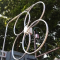

-
KiwiSDR production status and availability
I tested Master Electronics by ordering only a single enclosure. The process went flawlessly and the enclosure arrived as promised after 8 days.
They seem to be fine.
Glenn n6gn

-
External GNSS-disciplined rubidium input?
I know very little about the TDoA algorithm but I suspect both @jks and @Christoph are correct. Between the limited bandwidth and especially ionospheric propagation, typical Kiwi clock imperfection probably does not become an issue.
For an appreciation of this, you are welcome to examine the phase of one of NIST's transmitters received via a visual line-of-sight 20km path and displayed on a Kiwi having a ~.1 ppb (1e-10) GPS-disciplined external clock:
and by a different 'stock' GPS-corrected Kiwi at the same distance and also not receiving via the ionosphere:
Then have a look at a time/frequency signal via the ionosphere, CHU on 14670 kHz
(3) N6GN CHU 14670
or if conditions don't permit, perhaps 7850 kHz
Whether or not the the phase wander from the standard Kiwi in (2) causes significantly extra error compared to the bandwidth and sample-length restrictions and ionospheric variations would need to be examined more closely but I rather doubt it. Thus, improving the Kiwi's local clock probably wouldn't make much difference in the TDoA accuracy or resolution.
I think this is the primary reason that long-distance HF standard frequency transmissions tend to be only useful to .1 ppm. 1e-7, or so. Even though as-transmitted error may be 1e-12 the ionospheric path length is varying too much, particularly near the MUF for better accuracy.


-
Help with local interference
Presuming I have the correct K7GFH-associated Kiwi, at 1450 UTC you really aren't doing too badly. While I do hear a mains-related family of QRN from LF half way into HF, the levels aren't that terrible. Using the 10 kHz AM detector to allow hearing it (the individual lines tend to correlate and 'pop out' much more than in a narrower SSB bandwidth, they are found to almost completely disappear by 10 MHz leaving the Kiwi -154 dBm noise floor. This is assuming that the calibration is still about -16 and thus close to correct and no significant gain/attenuation on the way to the antenna.
The largest MWBC signal is around -30 dBm but there's no other station close to cause too much worry and there's no indication of OV.

Even at VLF you are hearing many stations pretty well, HI and Australia included. There's line related noise but I've seen far worse on many other systems. You're hearing well on 160m with several stations showing a lot of SNR.
Because this family of QRN starts so low rather than as modulation superimposed on a family of SMPS rate beginning higher up, I tend to suspect that it is rectification noise getting either back into the mains wiring or ground currents.
Here's a crude analysis of a little IQ/10kHz done by Audacity:

It does have 'ragged' edges around full-wave rectification (120 Hz) which may be what's responsible. I can't account for these.
OTOH, maybe the problem you are asking about has chosen this time to be absent.

-
QiwiQ a KiwiSDR client for Android: looking for feedback, testers and comments
I agree with @ZL2P that static buttons, while convenient, take away valuable screen real estate that is better spent on dynamic data such as spectrum and WF. I'd like to see grid lines for both axes, 10 dB/div for Y axis in spectrum and 5-10 in X axis at the zoom level.
I think the use of COL for spectrum is incorrect. IMO, COL can best be selected in WF by user to provide preferred contrast and characteristics, especially at low levels near the noise, but the corresponding amplitude information in spectrum mode should not be color as it presently is. Rather it should be vertical position - a spectrogram as on a spectrum analyzer. There is far more information conveyed with this sort of representation than with color.
WF is useful for gathering a temporal record, where that is important, but spectrum is a frequency record. Absolute and relative signal levels, noise and signal signatures are far better communicated in this mode with a Y axis that is amplitude. The WF color map can be used in spectrum as well, though even monochrome on a spectrum display can convey the same wealth of information.
I'd rather see the button space reduced, perhaps through drop-down menus, and the reclaimed display space used for spectrum and WF.
Thanks for making this nice app.

-
QiwiQ a KiwiSDR client for Android: looking for feedback, testers and comments
You ask a very pertinent question. I think the users and uses of a spectrum or WF display are varied so there isn't a single best answer. My own uses usually tend toward using it is a measuring device. But that can be in the process of improving ham station performance and also while operating the station to understand conditions and adjustments while making a contact. So my opinion is that both use models are important, though perhaps my main one is in the minority.
I understand the limits the phone environment puts on you and of course you're the best one to make trade-offs that stress these. However, I think what you already have running is very close to enough. Whether you run both WF and spectrum at the same time to me isn't critical. I'd be happy to select between the two based on my particular use case. The few simple changes to display of the data you are already presenting could, I think, make what you have even better for both measurers and operators alike. I don't think there's much additional cpu demand from the few changes I'd like to see, they are mainly static display characteristics of what you already have. I think they would make better use of the valuable display real estate available.
In the end only you know who and what your target audience is and what you'd like to do. I think the rest of us can only provide input suggestions, bug reports and thanks for your significant contribution to the utility of our Kiwis.
Best,
Glenn n6gn
-
QiwiQ a KiwiSDR client for Android: looking for feedback, testers and comments
IMO the logic is indeed broken. While other systems may have a 'default' CW offset of 500 or sometimes 600 Hz to create a "pleasing" tone, this may be most often with LSB tuning rather than right-side-up USB tuning. I'm not a heavy CW operator but it has always bothered me. I like to know where I've tuned my receiver and create a mental picture of what I'm hearing based on the mode I've selected. Thus I choose your solution when given a chance. But I am probably in the minority in many other ways, e.g. users seem to prefer WF over Spectrum views, temporal rather than frequency. While there are some cases that WF gives more useful information I think it doesn't remotely compare with a calibrated Y axis. Color simply doesn't provide the same information as a spectral display for me. Caveat emptor, I guess.
On an unrelated note, I did send you a pittance for a cup of coffee but haven't seen a registration key show up anywhere, I'm not even sure one is necessary. Is it?
Glenn n6gn
Fort Collins, CO
-
QiwiQ a KiwiSDR client for Android: looking for feedback, testers and comments
Another question: has anyone ever found an FM signal on the shortwave bands?
What is most common on shortwave: NBFM or NNFM?
You've no doubt had this question answered by now but, yes, there is significant NBFM activity between 29.5-29.7 MHz. I'm not certain it is well-controlled but it seems pretty comparable to the 'normal' (also varies!) 5 kHz peak deviation I hear on VHF.


