Quiet switch mode power supply (SMPS) for KiwiSDR

[from Peter, ZL2LD]
I have spent many hours testing different power supplies for the Kiwisdr and the new Kiwisdr2 radios.
My reference power supply for tests is a 12V lead acid battery with a 7805 linear regulator. It is ultra low noise but that’s not practical long term. I experimented with different power supplies (SMPS). I tried several different 5V Switched Mode Power Supplies (SMPS) and also made up a quiet supply using a 9V SMPS with a common mode choke and 7805 regulator with 1000MFD capacitor. The 9V/7805 was a lot quieter than the 5V SMPS but still not as quiet as the 12V battery/7805.
The SMPS noise is mostly visible at LF and lower frequencies.
I read that Apple make low noise phone chargers which makes sense when you consider that an iPhone has multiple radio receivers (mobile phone, Bluetooth, GPS, WiFi and NFC) and they want all those radios to operate well even while the phone is being charged.
I found a teardown review of the 20W USB-C iPhone and iPad charger where the reviewer looked at the noise on the DC output on a spectrum analyser. He then compared that to a no name Apple clone. The difference was huge.
So I went and bought a new Apple 20W USB-C power adaptor to test.
To get the USB-C to a 5V 5.5mm/2.1mm DC plug is a bit tricky. USB-C power supplies can communicate with the device being powered to output multiple voltages but without any data comms they can be forced to output 5V with a sense resistor. I guess that is so the powered device can get 5V to be able to get started then communicate back to the power supply.
To make it work to power a Kiwisdr I bought a USB-C male to USB A female adaptor. It must have the right sense resistor built in. These are very common as they are sold so people can connect old legacy USB devices to their flash new computer. Mouser have them in stock and they are a couple of dollars on AliExpress.
Then I had to get a cable with USB A male on one end and 5V DC 5.5mm/2.1mm plug on the other. You can probably buy these from a specialty electronics store. I got a couple from AliExpress. They were cheap but took three weeks to arrive. You can easily make it yourself. Most likely you will have an old USB A cable laying around that you can chop one end off. If you don’t have a spare 5.5mm DC plug you can probably find a dead or surplus power supply that you can chop off the DC connector with a short cable and join it onto the chopped USB A cable.
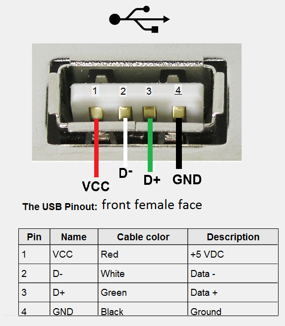
The wire colours in the USB cable are normally Red for +5V and black for -VE/GND but it is a good idea to plug the chopped USB cable into a USB socket and use a multimeter to check the 5V and ground. You solder the +5V to the centre pin of the 5.5mm DC plug and the -VE to the outer of the plug.
I also found a few sellers on AliExpress of USB-C male to 5V DC 5.5mm/2.1mm cables that does the whole job.
But if you want to get your new Kiwi running today then it will be much quicker to build your own cable.
The results on the spectrum scope were amazing all the way down to VLF. It is as good as the 12V/7805 battery reference supply.
If you only listen to good signals on 80m and up you can probably get away with any old 5V SMPS but if you want a nice quiet supply 0-30MHz it is worth using the 20W Apple supply.
P.S. I could not get the Kiwi to start on my nice quiet Agilent bench power supply as the Beagle gave one blink of a blue LED then refused to start. I suspect that the Beagle draws a high inrush current and the bench supply doesn’t respond fast enough so the power management chip “protects” the Beagle. I even tried adding some large caps on the supply output but it still would not start. It is a bit too fussy in my opinion. Just thought I would mention that in case any of you have similar issues.
Regards
Peter Munn, ZL2LD
Here is my complete power supply setup

Here is the USB A plug wiring if you want to use an ohmmeter to trace the wires.
Comments
I have read this message several times, but I have not understood its meaning. I also did a lot of experiments with different power supplies, and realized that there are three types of noise from SMPS.
1) The noise that KiwiSDR receives over the power cable. This has the weakest effect on the operation of the receiver. You can even ignore it. Power noise has almost no effect on the operation of the amplifier and especially the FPGA.
2) Noise from the operation of the SMPS power supply network, which propagate directly into the ether from the operating transistors and transformer have a more noticeable effect on the operation of the receiver. But, if your antenna is located more than 30 feet from this power supply, then you can also ignore this.
3) The worst thing is the emission of SMPS interference into the electrical network. Long wires entangle your home and stretch far beyond it. That's the main source of interference! Using a good mains filter is of great importance! And even more frightening is that interference to the electrical network can be caused by your neighbors and electrical equipment from various sources, such as factories and enterprises. But we will not be able to influence this!
Amazon has 5.5mm-F to USB-C male adapters X002BGA8XL
Hopefully Peter will be able to get on here and respond.
I have also tried several (about 10?) SMPS and one problem was always conducted noise on the primary side (230V). It would be interesting to know if the Apple power supplies do also have sufficient filtering on that side.
I feel confident to build filters for the DC rail, but not so much on the 230V side.
Currently I'm using 3 individual linear PSUs for the 3 kiwisdr but they aren't very efficient. It would be great if I was able to replace them with an efficient SMPS.
I use Meanwell MDR-60-5 and believe them to be clean.
CUI EMC-20 filters are also effective if the above is an issue
Both are relatively inexpensive
For those of us who upgraded to the BBAI-64 (original BB died), what about connecting the USB-C to the USB-C port on the BBAI-64?
I've found the USB port is cleaner than the DC port on the AI-64 for some reason, but both are still significantly worse than the BBG (main SNR used to be 32, now I can't get it better than 26).
I have done more experimenting and have now used three different style of Apple USB iPhone chargers including one of the old "duckhead" style 5V 1A chargers and a tiny USA "inch cube" style. The "duckhead" style has a removable head that can be interchanged for the four most common worldwide mains plugs (US. AU, EU and UK).
All three styles of the USB 5V 1A chargers I tested produce excellent results. They are easier to adapt to the 5.5mm/2.1mm plug required for the KiwiSDR than using the USB-C type. The other bonus of using the older USB chargers is that they were supplied for free with every IPhone and iPad for years. So almost every iPhone fan has one or more in their junk draw as they just seem too good to throw away. Even if you have never owned an iPhone, half your friends have them laying around and will probably give you one or more for free.
I found a great web site run by Ken Shiriff who tears down all sorts of electronics parts.
Here is a link to his teardown of the tiny "inch cube" USA charger. He has even drawn the schematic of the charger.
http://www.righto.com/2012/05/apple-iphone-charger-teardown-quality.html
Here are two screenshots of KwiSDRs showing the VLF spectrum. The top image shows the result using Apple 5V 1A supply and the bottom image shows the result using a Meanwell 5V supply.
The results show clearly that the Apple supply is 40dB quieter at 35kHz than the Meanwell supply. So unless you have an ultra low noise linear supply for your KiwiSDR I recommend you recycle an old Apple charger.
Of course those screenshots are with no antenna connected so most of the noise is from the power supply
Thank you for sharing your experience Peter, I'll give the Apple PSU a try.
Peter,
Which model Meanwell was used for that plot?
Surplus Lambda linear supplies are available on ebay all the time and they're not expensive.
Linear PSUs are not expensive, but electricity is ;)
My current linear PSU has an efficiency of 37%, the Apple PSU has 85%.
Following Peters comments, I have been experimenting with a few switched mode power supplies, and I have been trying to determine the factors contributing to noise ingress, by measuring RF noise present when using a variety of different makes.
There seem to be three elements that I have so far observed, some of which have already been outlined earlier in this thread.
Items 1 and 2 can be fixed by proper filtering of the PSU input and output, and also the use of screened cables.
Item 3 is more problematic. It tends to be most noticeable at the low frequency end of the spectrum, and is generally the result of some sort of ground loop, or loops, allowing any noise produced in the power supply, to find a route out, usually because the AC input and DC output are at different RF noise potentials. This combined with different external paths via the AC ground and DC ground, result in the noise being applied to the KiWi at different interfaces.
The remedy, is to ensure that the power supply AC input and DC output are all at the same RF potential. The mains input filtering requires both an X and a Y capacitor network, to ensure that all three conductors are at the same RF potential as each other. If no mains earth or ground connection is present, as is the case with a double insulated power supply, then the centre connection of a Y capacitor could be considered to be an internal common point. But this does raise serious mains safety and leakage issues, so care needs to be taken with this type of supply.
Most capacitors in such mains filters, can typically only use values of <1uF in order to ensure that they do not draw excessive current from the 50 or 60 Hz mains supply. In fact most are only in the region of 0.1uF, which does not really present a low enough value of impedance at LF RF frequencies.
The DC output is easier to filter with a capacitor, so that both the positive and negative (ground) wires are at the same RF potential as each other. Although once again it is difficult to filter out the fundamental LF switching frequencies with reasonably sized components.
Assuming both the AC and DC cables are filtered as above, and that the Y capacitor common point or ground connections of both are connected together inside the PSU, via a low impedance path. Then it should not be possible for RF noise to develop between the power supply AC input and DC output, and so any conducted common mode noise is unlikely to be propagated out of the supply.
These are just my observations so far, more work is required, and I invite any comments or corrections.
Regards,
Martin
I haven't connected the Apple charger to the kiwi yet. But I charged my phone with it, in the same room where the kiwis are and it is generating a bit noise in the spectrum from 100 to 200 kHz. I guess this is from the AC side. The DC side is too short to radiate significant noise on those frequencies.
The LF spectrum looks like this when I plug in the Apple charger:
I added a Schaffner FN2080 EMI filter in line on the AC side, which improves the situation on the 2200m-band by about 5 dB, but the noise floor is still about 5 dB elevated.
This would be the filter characteristics:
Meanwell MDR-10-5
Meanwell MDR-10-5 + EMI
Useful and fascinating discussion. What is pictured above, an emi filter? If so, which and where can it be ordered?
Thanks.
They are commonly available on Ebay from China at a very low price.
Get the version with the larger inductors marked 220 (22uH), as these will provide better filtering at lower frequencies.
Regards,
Martin
what a useful fact this is ~~
Apple 20W type-c is regarded to be a low cost but high efficient one, and I'm interested in pitting it against a linear PSU currently in use, for background noise in VLF/MW as comparison. 😀
The photo is for illustration purposes only, I bought versions with 220uH coils, 4A version
I did more tests with the Apple 20W supply. In the end I figured out how to get rid of the 100 kHz noise, but I don't know why that works. Maybe someone can give me a hint.
The antenna is a DC isolated inverted-L, with about 1000m worth of ground radials. On 100 kHz, my house is within the reactive near field.
The apple PSU is connected to a kiwi, which is NOT the kiwi where I'm receiving the noise and DC isolated from the other kiwis.
I put good CM/DM filters on the AC and DC side of the Apple PSU, which didn't do much. So I assumed it is radiated noise. On the DC side I can measure differential mode noise of about -30 dBm at 100 kHz, which shouldn't be enough to radiate into my antenna. I can't measure common mode noise properly, but it doesn't seem to be much.
Maybe stray magnetic fields from the transformer? On a H-field probe they seem to be very strong.
But now the good part. When I put the DC negative from the Apple PSU on protective earth (mains PE), the 100 kHz noise vanishes almost completely! But why is that?
I have been performing more tests and trying to understand the mechanism for the ingress of conducted noise from a power supply into the KiWi.
As I mentioned earlier in this thread I think there are three types.
Items 1 and 2 can be fixed by proper filtering of the PSU input and output, and also the use of screened cables.
Item 3 is more problematic. It seems to occur when a power supply has a noise differential between the AC input and DC output. It is almost like a transmitter feeding a dipole antenna. The AC mains forming one half of the antenna and the DC output forming the other half.
If we look at a typical KiWi installation it will be something like this.
By various mechanisms there will be a ground loop path between the KiWi antenna connections and the mains Earth. This allows noise from the AC side of the power supply to flow via the mains wiring and back by various ground paths, until it reaches the KiWi RF input grounds.
This forms a loop so that any noise differential is applied indirectly to the KiWi DC and RF ground connections, which are at opposite sides of the KiWi PCB. So the Noise differential appears across the KiWi RF circuits.
As a result I decided to try and evaluate various DC power supplies in terms of the Noise differential between their AC input and DC output.
This was the test circuit I developed.
By using a mains input filter to tie all the mains wires to the same RF potental, a broadband RF isolating transformer and a 'floating' load. I was able to exclude any unwanted ground loops, and concentrate on just the noise differential produced between the Power Supply AC input and DC output.
Note that I included an external 10dB attenuator at the Spectrum Analyser input in order to better protect it under fault conditions.
Here is the resultant Spectrum Analyser plot of three different Switched Mode Power Supplies.
The Apple and Blackberry were 5v 5w 'plug top' style chargers. Note that an Apple (or any other) 20w USB charger may only operate in 5w mode by default, unless commanded by the device it is powering to supply more output.
The Meanwell was a 'brick' style plastic cased charger with an integral IEC mains socket. I had modified this to include additional DC filter components, and improved the earth bond between the AC input and DC output by adding a brass screen over the top side of the PSU PCB.
Both the Apple and Blackberry chargers were relatively quiet in comparison to some unbranded Chinese chargers that I tried. I have not included those as they were above the top reference line on the scale I have used.
As I have shown it is possible to reduce this form of conducted noise by having a low impedance bond between the AC input and DC output of the power supply, so that it is harder to develop a noise differential between the two.
However the addition of a DC EMI filter of the type previously mentioned, that has a series inductor in both the positive and negative DC power lines, will also help increase the overall loop impedance so that less noise current can flow.
Regards,
Martin
@HB9TMC I think you made a good point.
Even though a PSU may have a metallic mains earth connection (but many don't), I think it is worthwhile connecting the DC negative to the mains earth at the point the PSU is plugged in.
In addition some USB earth screen connections are not actually wired to anything inside the PSU, and some USB leads either don't have a screen, or the screen is not connected at both ends.
As I previously stated I think that the AC and DC cables need to be at the same RF potential, and this is why your earth modification is proving to be effective.
I'll see if I can repeat your suggestion and measure any differences, to try and support this theory.
Regards,
Martin
Although, connecting PE directly to DC- might make things also worse, since there might be noise on PE.
I have the DC input now filtered like this, which seems to be blocking any PSU noise.
Agreed, connecting the PE and DC negative may allow other noise external to the PSU, but present in the ground loop to be introduced.
Using an AC filter with a choke in the PE line, may help to resolve that issue.
Regards,
Martin
I bought a coupe of these USB-C to 5.5mm DC cables from Aliexpress and they are useless. I only get 1.7V from the 20W Apple USB-C charger with no load. USB-C chargers are smart. They expect commands from the device being charged to specify power and voltage.
These USB-A to 5.5mm cables from Aliexpress work perfectly with Apple iPhone chargers and only cost a couple of bucks including freight
We have found a problem with the very small USA Apple Iphone chargers. The sample I have here ran the Kiwi fine but when John did a remote code update it kept resetting so it must be marginal when the Beagle drew a bit more power as part of the download process. The update worked fine when I used the other two versions of Apple chargers that I have. This is only a single sample test so your experience might vary. Here is a photo of the USA mains plug model that couldn't handle the code update.
I'm sure you all know that the aftermarket counterfeit Apple chargers should not be used with a Kiwi as they can be very noisy.
Regards - Peter ZL2LD
When I try the 5.2v 2.4A /5.1v 2.1A Apple charger, the kiwi starts up for a short time (even with ethernet on, but no ping reply) but then keeps rebooting. Any suggestions?
73, Jim PA8E
Hi, Jim. Are you sure it's a charger related problem? Did you try another power supply? (Even if noisy, it should be good enough for a test.)
@jnijkamp
Do you have connected the power supply to the kiwi or the beagle board?
IIRC the beagle board can't deliver enough current for the kiwi if it's powered from the usb port.
DL7AWL: I use an old LinkSys adapter (5v, 2a) which works fine. But it's far from clean, so that's why I tried an Apple charger.
HB9TMC: I use the 5.5mm plug in the kiwi.
I bought what was supposed to be the Apple power supply and results not good in AM broadcast band. Maybe mine from Ebay was a clone/fake.
Put on my PS1502DD linear supply I bought years ago from Ebay and presto, very quiet, no noise at all now.
With the Apple supply, I could hook another separate SDR-14 to the antenna of the KIWI 2 and hear trash coming out of the antenna in Broadcast band and up! With the linear supply, no difference with antenna from SDR-14 connected to the KIWI antenna.
Have mine now up with a 3 ft mag loop mounted way in the back yard, away from house EMI and working very well.