The KiwiSDR 2 online store is open for orders! Please visit kiwisdr.nz
Please visit kiwisdr.com (documentation) and kiwisdr.nz (online store)
Kiwi-1: How to fix a shorted 5V input CMC (T301)

@n6gn It's also possible to pop the plastic top of the CMC with a thin flat blade screwdriver, cut the winding connections two at each end and jumper lengthwise in place of the disconnected windings.
This avoids having to heat up the pads to remove the entire CMC - a rather difficult process without the right desoldering equipment.
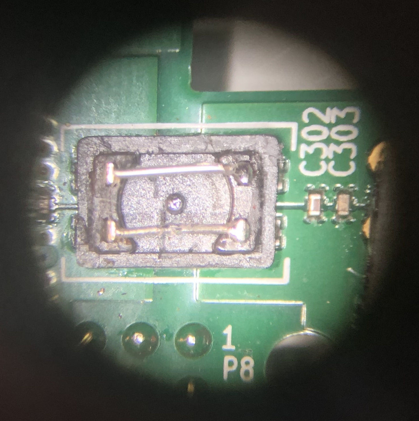
I needed to fix a broken Kiwi I've had sitting around here for years (customer return). Sure enough, a shorted T301 CMC.
I tried Glenn's trick and it worked great. The cover pops off easily and even snaps back on after you've jumpered the pins. Microscope photo prior to soldering left-side pins: Thanks Glenn!
Comments
@jks I really want to know how you get off the plastic top from the CMC, i have the same problem but i get the top not loose.
If you look carefully, perhaps with some magnification, you'll see there is a seam in the plastic of the part. The seam runs all the way around the part, just down slightly from the top.
Use a small sharp knife, like an X-ACTO knife, to pry the top of the part off. Just stick the knife in the seam and twist. The top should pop off. It's just held in by friction (and maybe a little bit of glue). This is why you're able to snap it back on afterwards.
You might also be able to use a small screwdriver instead of a knife.
@jks Thanks, i will try again
My Kiwi just died, there is a short circuit, the 501Y choke is getting very hot and it smells of burning. After opening you can see this:
Now the question: is it enough to pick out the burnt choke and make a bridge as in the first photo in the topic for it to work?
Yes, definitely.
Was it powering a BBG/BBB or BBAI/BBAI-64 through that connector?
BBG and I am sure that I broke it when I forgot to reduce the transmitter power and AGC at the input during the test, I only heard the grating of the distorted RF signal in the headphones. and several hundred W went through the cables, despite dozens of ferrite cores fastened wherever possible, the one lying closest to it died. I used LED legs for the bridge, everything works!
Okay, that's great to hear!
Hello, i already mentioned that my T 301 CMC was burnt ( my own fault) from my Kiwi 1 , but when i tried to repair it with the messages here posted i broke of the CMC. Is it still possible to make a bridge? I told early its is now powered through the mini-usb and that works oke for the moment. So is bridge still possible?
A bit difficult to tell from that photo, but it seems the PCB pads have been torn off. In that case about all you could do is solder a wire from the positive lug of the DC jack to the 5VE pin on the P9 header. Not the easiest thing to do. But possible.
Several people have mentioned their Kiwi will run when powered from the BBG micro USB. This is surprising because the power on that port is supposed to be limited to 500 mA by the PMIC and that is nowhere near enough to run the BBG + Kiwi board together. There is a jumper you can make on the BBG to override this restriction. But it is not enabled by default.
@jks Thanks, perhaps i will try that. For now i power through the mini-usb and it works perfectly.
@jks Hello, sorry only want to know which ot the two 5VE on the P9 i must use. Then i can make the bridge. Many thanks and greetings.
That doesn't matter. Both are connected together anyway.
Due to the missing CMC choke, not only the +5V line is interrupted, but also GND. So in addition to the 5 V wire described by John you need also to make a GND wire from the DC jack (outer sleeve) to kiwi's GND (Pins 1/2 on P9, for example).
@dl7awl oke thats not difficult but connect the both pins or only one pin? Is that also with the 5VE pins?
Yes, the same. Look at the copper traces near these pins on the kiwi and/or beaglebone; maybe it's visible that both +5V pins are directly connected and both GND pins as well. So it doesn't matter which one you use in each case.
Background: The GND and +5V rails (and some others) are each using two pins in parallel on the P9 connector in order to be able to handle higher currents while keeping the voltage drop low.
Be sure to count the pins correctly and double-check your wiring! Any mistake can destroy something! [Beagle connectors]
By the way, I'd suggest to power the kiwi again via mini-usb for the first time after making the wire connections. So if you should have made a mistake, the current is kind of limited and has less destructive potential. If then all works as before, you can dare to apply 5V to the kiwi's DC jack.