The KiwiSDR 2 online store is open for orders! Please visit kiwisdr.nz
Please visit kiwisdr.com (documentation) and kiwisdr.nz (online store)
Out of band signals from 39-45 MHz on kiwisdr 2 [fixed with external LPF]

Hi all,
Need some advice dealing with out of band signals.
Some background: My area has NFM transmissions in the 39 to 45 MHz range. I'm running a 40 foot longwire outdoors attached to a 9:1 balun and the balun is attached to a common mode choke. The coax feedline is 25 feet. Antenna height above ground is less than 10 feet. The kiwi is powered by a battery.
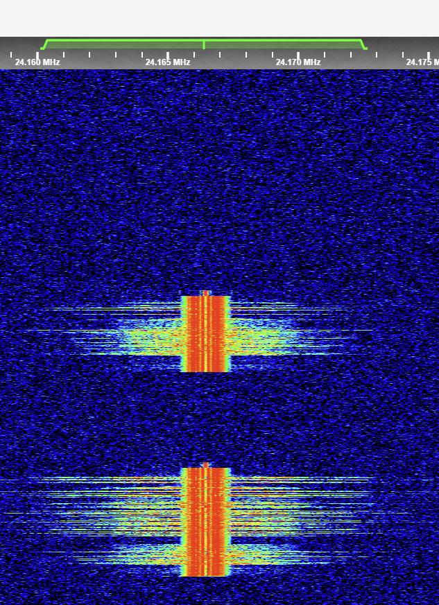
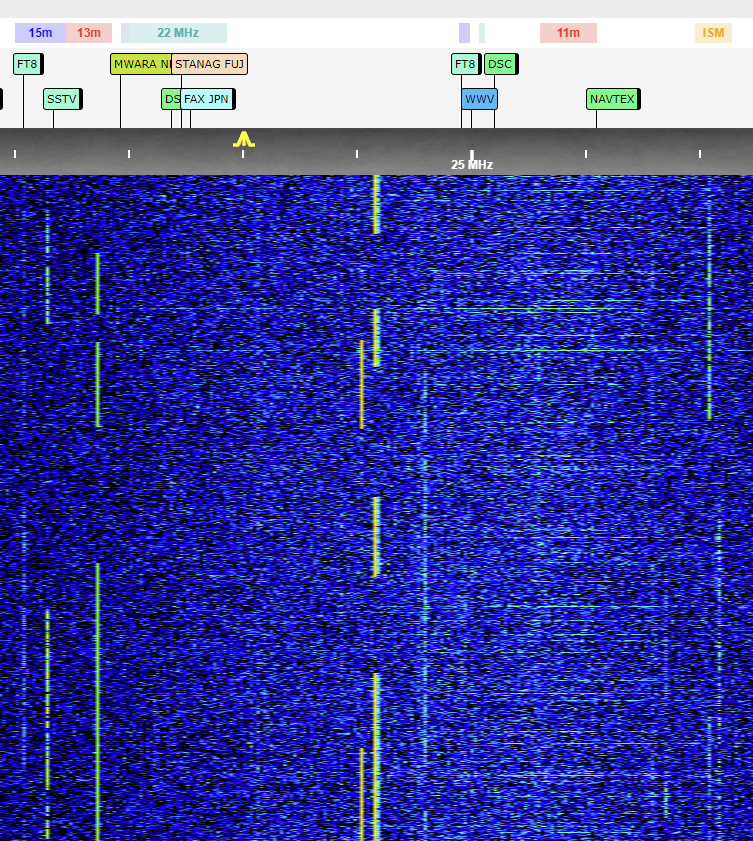
Checking to see on what's the best way to eliminate out of band signals that are coming from the 39 to 45 MHz range and appearing in the 21to 24 MHz range. The signal is NFM tunable and audible. Attached are two screenshots.
Comments
It would be interesting to see the spectrum display (including the dB scale on the right) as well as peak S-meter readings with the passband centered on the signal. It's impossible to judge the strength of these signal looking at the waterfall alone due to colormap calibration.
Unless these signals are extremely strong I'm surprised they're getting through the 30 MHz LPF in the Kiwi frontend (7th order Chebyshev). You might have to resort to a high-Q notch to get rid of them.
Attached is another screenshot. The signal peaks around -80 dB / S7-S8. The actual transmission of this signal is 42.5 MHz and it's appearing on 24.166 MHz on the Kiwi 2. There are several other signals that peak from -110 to -90 dB. These are repeater output signals that can be heard from a 25+ mile / 40+ km radius using a scanner and a rubber duckie antenna.
I don't have a separate notch but I can try a different type of antenna to see if it helps.
I had a sig gen (hp 8657) connected to a Kiwi for other reasons. So tried a few things:
Kiwi-1, 42.5M in, 24.166M out, 21 dB down
Kiwi-2, 42.5M in, 24.166M out, 24 dB down
Kiwi-1, 47.5M in, 19.166M out, 31 dB down
Kiwi-2, 47.5M in, 19.166M out, 33 dB down
So the Kiwi-2 is slightly better. 24 dB is not a huge amount of attenuation though. I measured the same difference in levels with sig gen settings from -90 to -40 dBm.
I also carefully calibrated the S-meter and waterfall/spectrum using the two cal values on the admin/config page. S-meter cal needed to be -16 to get -73 dBm (S9) at 14M. And WF cal -11 to get -73 dBm in the spectrum display as shown by the mouse cursor popup (CW passband in all cases).
So yeah, at 42.5 you're going to need some extra targeted attenuation.
Thanks for the measurements. I tried a mag loop and the signal peaked at S9+ 10 so that didn't help. I'll probably try a low pass filter with a cutoff at 30 or 32 MHz and might need to connect a couple of them in series.
Out of interest, how does that happen?
42.5+24.166 = 66.666
47.5+19.166 = 66.666
So that is mixing with the ADC clock I assume, but where? Is that aliasing?
The ADC is just under-sampling stuff above Nyquist. That's why you often find ADCs with huge input bandwidth specs way in excess of their sample rate capability. With the right image filtering ahead of the ADC the Kiwi could under-sample stuff above 30 MHz no problem.
But of course you can't process more than one sampling band without them imaging together. Which is the problem seen here.
I'm not sure where you are located, but I think you have been unlucky to encounter this problem.
I monitor the VHF Low bands, and would be interested to know what you are hearing.
http://wessex.hopto.org:8075
Generally speaking, the Low VHF bands are not that busy, and from memory the only similar report of this type of issue was associated with local amateur transmissions in the 50MHz (6m) band.
You can easily obtain cheap 30MHz LPF's that are intended for use with 27MHz CB radios, but these may not provide enough out-of-band rejection at 40Mhz.
I think John is correct, because of the close frequency relationship between the KiWi 30MHz LPF turnover frequency and the 40MHz signals. You may be able to obtain greater rejection by using a notch filter tuned to the ~ 40MHz signals instead.
However, if you can construct RF circuits, then a modified Cauer LPF may be worth trying.
A bit of experimentation and tweaking of values using Elsie filter designer
https://tonnesoftware.com/elsie.html
resulted in this circuit, which is a reasonable trade between the stop band attenuation, number of parts and eventual fine tuning of a practical circuit to achieve the predicted response curve.
Regards,
Martin
That's an interesting circuit that I might try if an off the shelf filter is not good enough. I'm on the east side of the San Francisco Bay, California, USA. These are highway patrol dispatch signals that have a large geographic reach that is comparable to an FM broadcast station. What's interesting is that there's a Kiwi station with a large antenna on the west side of the bay that does not seem to be affected though I don't know if it has a notch or low pass filter attached: http://69.27.184.58:8073/
You have some nice setups there in the UK. Mine is not up yet until I figure out a more permanent location.
The Utah Web sdr's have very large antennas, and a complex distribution system with lots of additional filters.
This is an example of a distribution diagram for the Northern Utah web sdr's.
Regards,
Martin
That is certainly impressive and meticulous. The SDR rabbit hole is almost endless.
Funny enough, am on the east side of the bay in Oakland, and I have recently been noticing the exact same thing, that I'm picking up CHP low band on the kiwi2 somehow.
I picked up a Mini Circuits BLP-30+ filter to test. It does knock down the CHP signals quite a bit but not completely.
Unfortunately, a single Mini-Circuits LPF may not have a sharp enough cut-off.
Approx. 10dB attenuation at 40MHz and 30dB at 50MHz
https://www.minicircuits.com/pages/s-params/BLP-30+_GRAPHS.pdf
Regards,
Martin
This one has a sharper cutoff and a 45 dB rejection at 41 MHz but the rolloff starts around the 10M band.
https://www.minicircuits.com/pdfs/BLP-27+.pdf
I'd be tempted to try that one.
The roll off is quite steep, and the loss over the amateur part of 10m is not too bad.
However, the Comet CF-30MR seems to be an option, as it has a claimed 50dB attenuation at 40MHz. Note not the CF-30S version, which is poor.
You may be able to find a second hand one at ta decent price if you search on-line.
Regards,
Martin
I have one on order. I do rather have zero phantom signals than a slight rolloff at 10M.
The spectrum shown here for Paul WB6CXC's 4-element Elliptic 30 MHz LPF is pretty spectacular: turnislandsystems.com/test-results-shelving-low-pass-filter
This one did the job: https://www.minicircuits.com/pdfs/BLP-27+.pdf