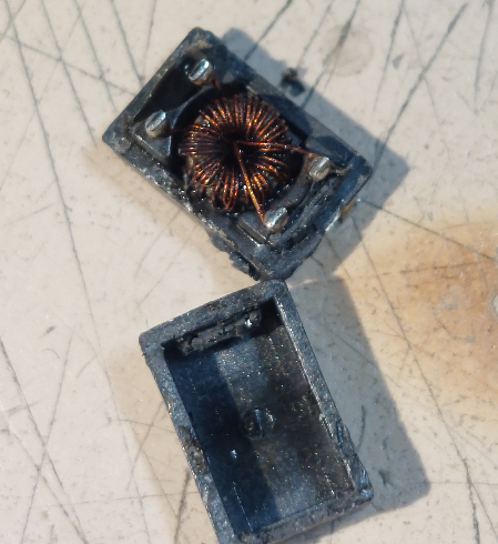
KiwiSDR HW failure - input filter inductor failure
[I'm posting this to General Chat because I don't see a more specifically HW discussion. Move this as appropriate.]
After several years of continuous operation, I've had the first 'stock unit' failure of any of my several Kiwi's. The problem exhibited itself by the Kiwi drawing way too much current such that the PS dropped to a couple of volts. To diagnose, I separated the BBG from the Kiwi PCB and applied power to just the BBG through the same pins the KiwiPCD uses. The short/low resistance disappeared and the BBG ran normally. Turning to the Kiwi I found <1 ohm across the power terminals. Visually examining the four capacitors and suspecting the inductor as the culprit (from experience with BBAI/Kiwi failure of the part at high current) I used a hot air station to pull the inductor off the PCB. I found the part to appear nearly shorted. It and it's plastic housing looked like ithey had probably overheated.
I next jumpered the SMD pads on the PCB, reassembled the Kiwi/BBG and powered up. Everything ran normally again.
My interpretation of the failure mode is that this differential filter runs too hot in a standard Kiwi and even moreso when a BBAI rather than the stock BBG is being powered through it.
So this is not a complaint but ust a heads-up that if your Kiwi either stops pulling current or else pulls way too much, that separating the Kiwi from the BB and measuring might be a really good place to start troubleshooting since this inductor really does seem to run too hot even in a stock unit.
I think that this component is actually not necessary at all and seems to have no measurable effect on Kiwi performance and PS rejection. The PM IC in the BB is intermediate to the KiwiSDR PCB and seems to take care of any issues that this filter might help to improve. Of course one could also replace with a higher current filter L but I've never found it to be worth the effort.
Glenn n6gn
Fort Collins, CO
[edit]
In considering it further, I think if I find I need to replace or remove this filter, perhaps to increase reliability for operation at a remote site, I might try leaving the package soldered to the PCB and simply removing the plastic housing using a jewelers screwdriver to pry the top away from the bottom. The two pieces seem to be fastened together with a flexible adhesive so they come apart pretty easily. Then simply cutting the leads from the inductor and soldering two jumpers across the terminals (in the long dimension) removes the need for a hot air solder station and is also probably quicker.


Comments
Maybe just leaving the package open will help with air cooling and the coil will not get burned.
DC supply discussed here
https://forum.kiwisdr.com/index.php?p=/discussion/comment/12058#Comment_12058